A telescopic foot lock adjustment mechanism

A technology of adjusting mechanism and telescopic feet, which is applied in the direction of building structure, scaffolding accessories, housing structure support, etc., can solve the problems of few adjustment gears and troublesome operation, and achieve the effect of increased convenience of use and high locking reliability

Active Publication Date: 2017-01-18
小巨人公司
View PDF5 Cites 0 Cited by
  • Summary
  • Abstract
  • Description
  • Claims
  • Application Information

AI Technical Summary

Problems solved by technology

[0004] The purpose of the present invention is to provide a telescopic foot lock adjustment mechanism, which solves the problems of less adjustment gears and troublesome operation in the prior art

Method used


Image

  • A telescopic foot lock adjustment mechanism
  • A telescopic foot lock adjustment mechanism
  • A telescopic foot lock adjustment mechanism

Examples


Embodiment

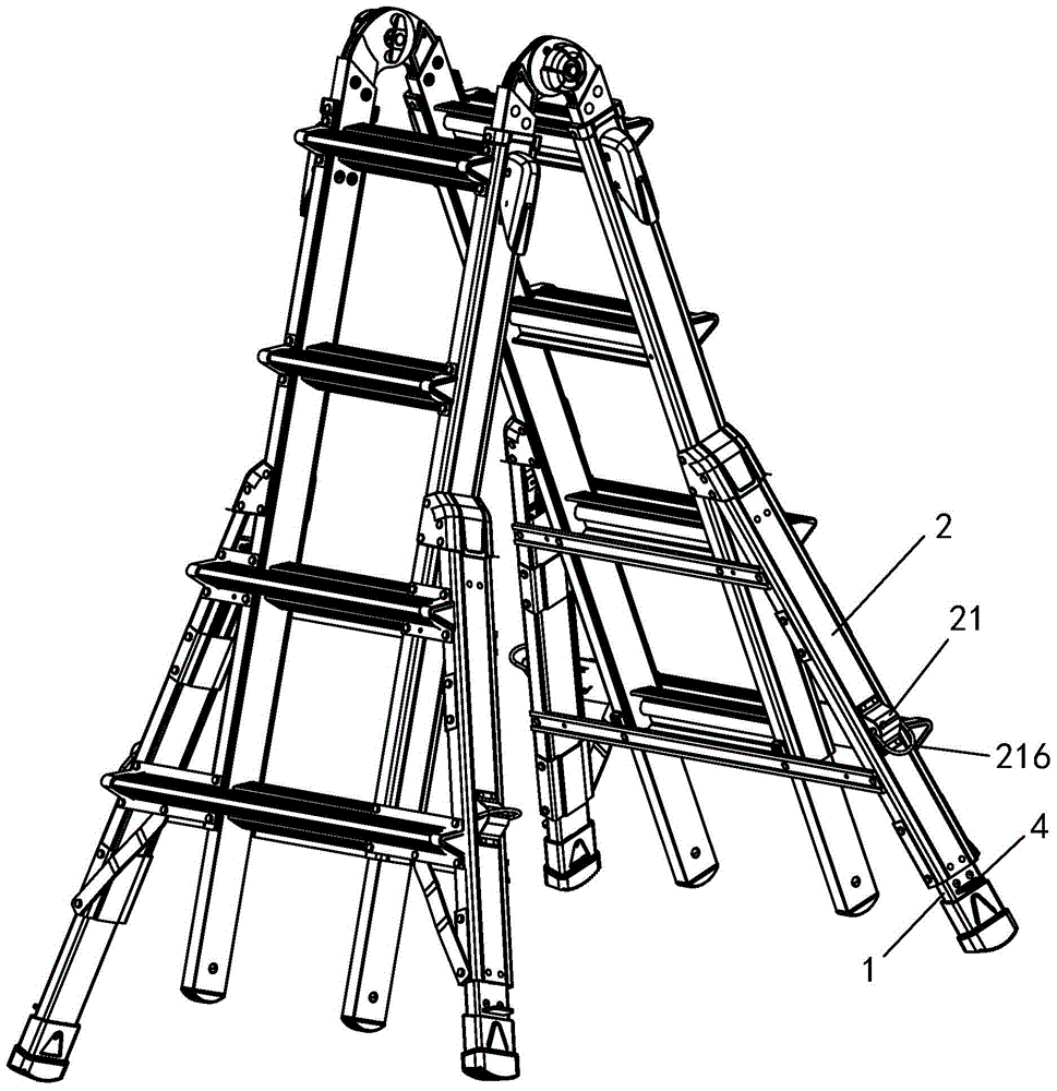
[0022] Example: such as Figure 1 to Figure 5 Shown:

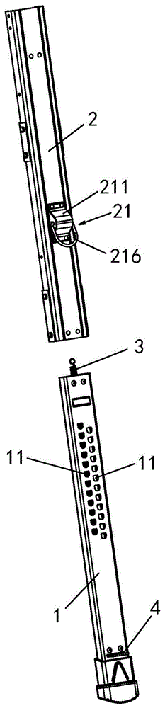
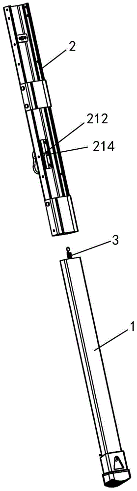
[0023] A buckle adjustment mechanism for telescopic feet, comprising a positioning hole 11 opened on a telescopic foot 1 and a buckle 21 correspondingly installed on a fixed foot 2 .

[0024] The telescopic foot 1 is slidably embedded in the fixed foot 2 along the length direction.

[0025] The positioning holes 11 are two parallel rows of positioning holes, each row of positioning holes 11 is arranged along the length direction of the telescopic foot 1, and the two rows of positioning holes 11 are misaligned in the length direction of the telescopic foot 1, see figure 2 and Figure 5 .

[0026] The buckle 21 is composed of a support 211, a first pin 212, a first elastic element 213, a second pin 214, a second elastic element 215 and a pull ring 216. The support 211 is fixed on the fixed foot 2, The first pin 212 and the second pin 214 are arranged side by side on the support 211, the first elastic element 213 acts on...


PUM


Abstract

A telescopic foot lock adjustment mechanism, comprising a positioning hole (11) opened on the telescopic foot (1) and a corresponding lock (21) installed on the fixed foot (2), characterized in that: the positioning hole (11) Two rows of positioning holes are parallel, and the two rows of positioning holes (11) are misaligned in the length direction of the telescopic foot (1); the lock (21) is composed of the support (211), the first pin (212), the first elastic element (213), the second pin (214), the second elastic element (215) and a pull ring (216); the first pin (212) and the second pin (214) alternately cooperate with the positioning hole (11) to form a locking State: pulling the pull ring (216) by an external force can make the heads of the first pin (212) and the second pin (214) withdraw from the positioning hole (11) to unlock. The invention has multiple adjustment gears, convenient operation and high locking reliability.

Description

technical field [0001] The invention relates to the fields of ladders, scaffolding and workbenches, in particular to a telescopic foot lock adjustment mechanism for ladders, scaffolding and workbenches. Background technique [0002] In order to adapt to conditions such as uneven ground, the feet of ladders, scaffolding, and workbenches are often designed as telescopic feet, that is, a fixed foot is embedded with a telescopic foot, and the telescopic foot can slide and stretch along the length of the fixed foot. A locking mechanism is used to realize the locking of the telescopic position of the telescopic foot relative to the fixed foot. [0003] For the prior art, please refer to the utility model patent whose Chinese patent announcement number is CN202157739U. This patent discloses a three-leg telescopic ladder, the telescopic foot structure is composed of a casing (i.e. a fixed foot), a telescopic foot and a hook pin positioning mechanism. , elastic elements and multipl...

Claims


Application Information

Patent Timeline
Patent Type & Authority Patents(China)
IPC IPC(8): E06C7/50E06C7/42E04G5/02
Inventor 谢小燕
Owner 小巨人公司
Why Eureka
Try Eureka