
Display device

A technology for display devices and assembly holes, which is applied in the direction of lighting devices, fixed lighting devices, lighting device components, etc., can solve the problems of increasing the installation operation process, difficult stability, and reducing the production efficiency of the whole machine, so as to achieve simple installation, The effect of installation and snapping is stable

Active Publication Date: 2015-11-11
HISENSE VISUAL TECH CO LTD
View PDF13 Cites 2 Cited by
  • Summary
  • Abstract
  • Description
  • Claims
  • Application Information

AI Technical Summary

Problems solved by technology

[0003] In view of the appearance and fixing problems of the above lighting parts, some all-in-one machine structures can realize the fixing of the lighting parts by increasing the width of the lower frame of the front shell, but for some structures, there is little space reserved for the lower frame of the front shell, and the lighting When the parts are fixed by buckles, it is necessary to pre-embed the buckle parts in the lower frame of the front case, but because there is little space reserved for the lower frame of the front case, it is difficult to realize or the stability of the lighting parts is poor after snapping. In order to increase the stability of the lighting parts The stability is usually supplemented by screw fixing, which increases the installation operation process and greatly reduces the production efficiency of the whole machine

Method used


Image

  • Display device
  • Display device
  • Display device

Examples


Embodiment Construction

[0018] The following will clearly and completely describe the technical solutions in the embodiments of the present invention with reference to the accompanying drawings in the embodiments of the present invention. Obviously, the described embodiments are only some, not all, embodiments of the present invention. Based on the embodiments of the present invention, all other embodiments obtained by persons of ordinary skill in the art without making creative efforts belong to the protection scope of the present invention.

[0019] In the description of this application, it is to be understood that the terms "center", "upper", "lower", "front", "rear", "left", "right", "vertical", "horizontal", The orientations or positional relationships indicated by "top", "bottom", "inner", "outer", etc. are based on the orientations or positional relationships shown in the drawings, and are only for the convenience of describing the application and simplifying the description, rather than indic...


PUM


Abstract

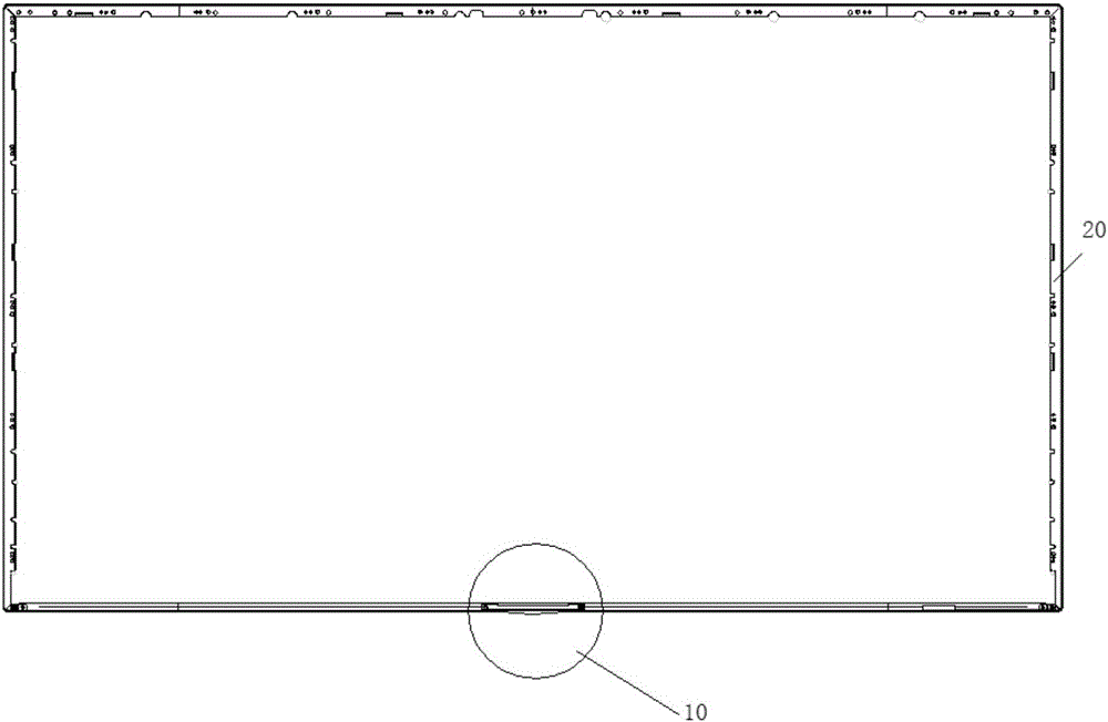
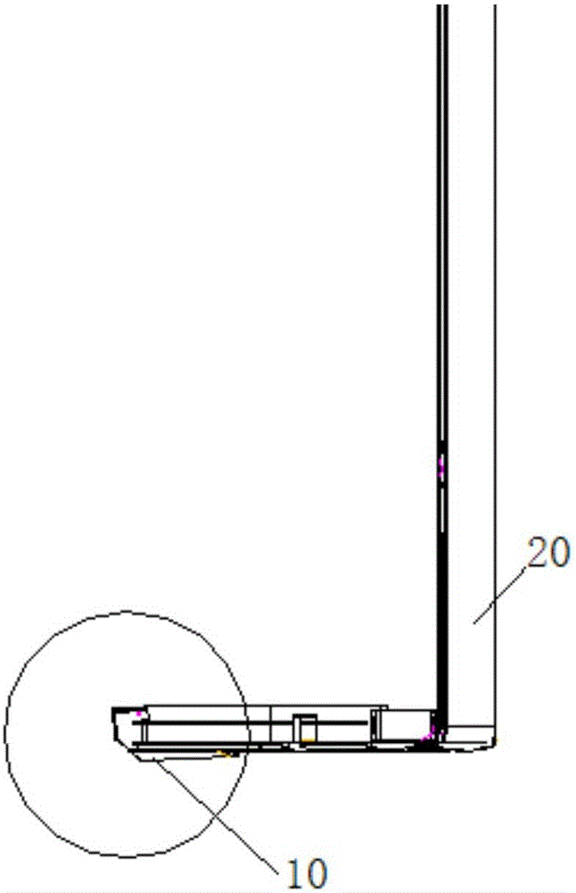
The embodiment of the invention provides a display device and relates to the field of display equipment. By the adoption of the display device, a lighting component can be easily installed and stably clamped. The display device comprises a front shell, a rear shell and the lighting component. The lighting component comprises a light bar and a light guide plate, wherein one end of the light guide plate is provided with a concave light groove, the light bar is arranged in the light groove, and the extending direction of the light groove is perpendicular to the extending direction of the light guide plate; two mounting holes are formed in the two ends of the light groove in the two extending directions of the light groove, and each mounting hole is open in the extending direction of the light guide plate. Two riveting pillars are arranged on the frame of the front shell, and the riveting pillars are inserted into the mounting holes. The edge of the rear shell is abutted against the outer wall of the light groove of the light guide plate. The display device is used for display device assembly.

Description

technical field [0001] Embodiments of the present invention relate to the field of display devices, and in particular, to a display device. Background technique [0002] Lighting parts can be called the eyes of LCD TVs. Diversified lighting parts can make customers' eyes shine and be attracted instantly. There are usually two ways to fix lighting parts: by screws or by buckles. The former is usually applied to metal frames, and the latter is more common on plastic frames. At present, ultra-thin lighting parts are a common trend. How to fix and cooperate the ultra-thin lighting components with the ultra-narrow and ultra-thin frame is also a direction of technical research and development. [0003] In view of the appearance and fixing problems of the above lighting parts, some all-in-one machine structures can realize the fixing of the lighting parts by increasing the width of the lower frame of the front shell, but for some structures, there is little space reserved for the ...

Claims


Application Information

Patent Timeline
Patent Type & Authority Applications(China)
IPC IPC(8): F21S8/00F21V17/10F21V19/00
CPCF21S8/00F21V17/10F21V19/00
Inventor 周洪亮迟寿林郭安民孙耀民张王军
Owner HISENSE VISUAL TECH CO LTD
Learn More