

Food management device and method and refrigerator
A technology for food management and refrigerators, applied in household refrigeration devices, lighting and heating equipment, supports, etc., can solve the problems of high cost and inconvenient food detection, and achieve the effect of low cost and high practicability
- Summary
- Abstract
- Description
- Claims
- Application Information
AI Technical Summary
Problems solved by technology
Method used
Image

Examples
Embodiment Construction
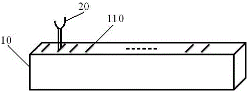
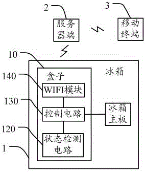
[0034] The invention provides a food management device, method, and refrigerator. The box is matched with the attachment, and the attachment is taken out of the box and put into the refrigerator together with the corresponding food. The status information of the removal and replacement of the attachment is identified through the box and uploaded to the server. On the server side, the attachment and the food can be identified accurately to identify the presence or absence of food in the refrigerator, achieving better food detection results. It is very convenient to use (just take it out and put it back on the attachment), and has strong practicability and reliability. In order to make the object, technical solution and advantages of the present invention more clear and definite, the present invention will be further described in detail below with reference to the accompanying drawings and examples. It should be understood that the specific embodiments described here are only us...
PUM
 Abstract
Description
Claims
Application Information