Multibeam depth measuring sonar multi-subarray wave beam sharpening method

A sounding sonar and beam sharpening technology, applied in radio wave measurement systems, instruments, etc., can solve problems such as large computational load, difficult real-time implementation, and hardware complexity, and achieve high main sidelobe ratio and high engineering practicality. the effect of reducing the width of the main lobe

Active Publication Date: 2015-11-11
HARBIN ENG UNIV
View PDF3 Cites 9 Cited by
  • Summary
  • Abstract
  • Description
  • Claims
  • Application Information

AI Technical Summary

Benefits of technology

This technology improves upon previous methods by reducing computational complexity while still maintaining good performance at smaller sizes compared to traditional techniques like LMS (Least Significant Squares) or FFT algorithms. By performing this technique without adding extra weight values, we aim to improve the overall efficiency of signals processed through an antenna system.

Problems solved by technology

The technical problem addressed in this patented technology relates to improving the performance (accuracy) and reliancy of ultrasonic wave detectors used in multiple-bearn sonars during underwater scanning operations due to their broadband characteristics. Specifically, current techniques have limitations including narrow band effects caused by sea surface waves, low sidelobular levels, and reduced space resolution resulting from tunneling between different directions. There needs an improved technique called Multi-SubArray Beam Sharping (MSBS), which combines signals from various sources together without overlapping them.

Method used


Image

  • Multibeam depth measuring sonar multi-subarray wave beam sharpening method
  • Multibeam depth measuring sonar multi-subarray wave beam sharpening method
  • Multibeam depth measuring sonar multi-subarray wave beam sharpening method

Examples


Embodiment Construction

[0038] The present invention is described in detail below in conjunction with accompanying drawing:

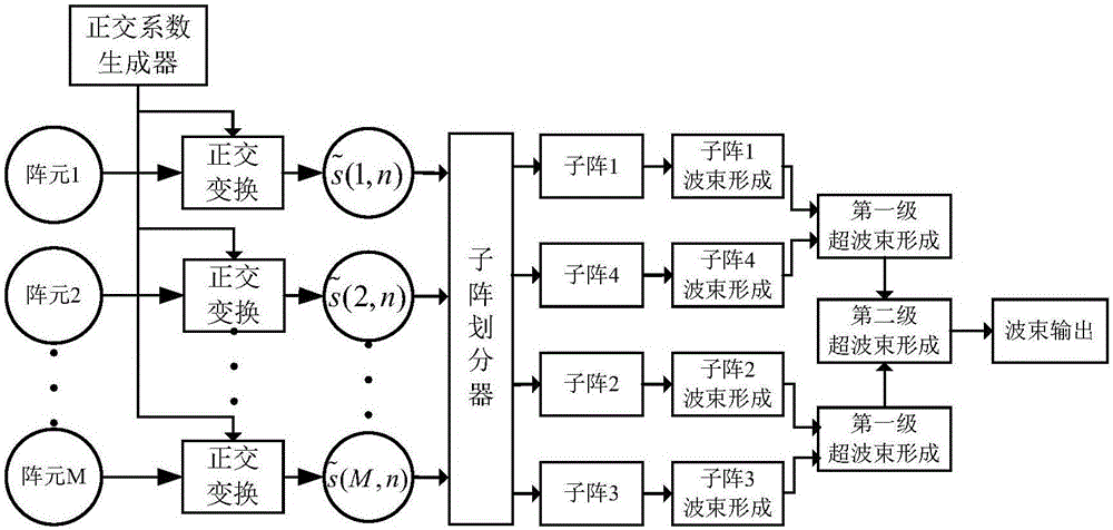
[0039] A multi-beam sounding sonar multi-subarray beam sharpening method comprises the following steps:

[0040] Step (1): performing orthogonal transformation on the original signal received by the transducer array to obtain the required analytical signal;

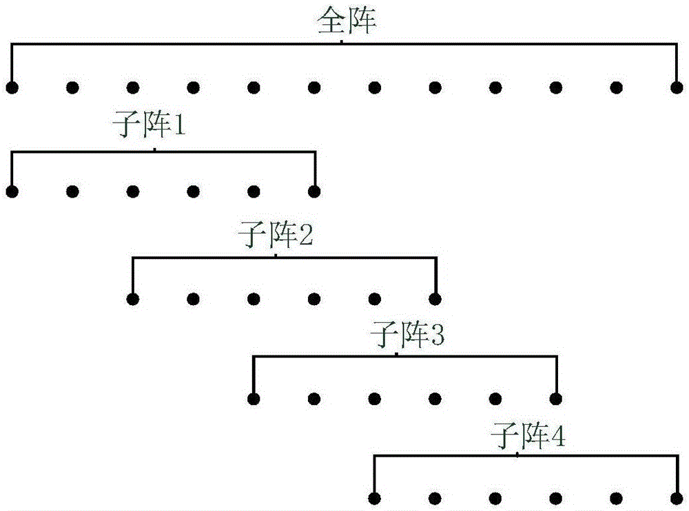
[0041] Step (2): Utilize the subarray divider to divide the obtained analytical signal into subarrays, divide the signal into 4 subarrays with a certain overlap in space, and divide the subarrays into 2 subbeam groups;

[0042] Step (3): Perform conventional beamforming on each subarray, and perform first-level sharpening beamforming on subbeam group A composed of subarray 1 and subarray 4 and subbeam group B composed of subarray 2 and subarray 3;

[0043] Step (4): The sharpened beamformed output of sub-beam group A and sub-beam group B is used as the input of the next level of sharpened beamforming, and the second leve...


PUM


Abstract

The invention relates to a multibeam depth measuring sonar multi-subarray wave beam sharpening method. The method comprises the following steps: carrying out orthogonal transformation on original signals received by a transducer array to obtain needed parsing signals; by use of a subarray divider, carrying out subarray division on the obtained parsing signals to divide the signals into four subarrays overlapped in space and divide the subarrays into two sub wave beam groups; carrying out routine wave beam formation on each subarray, and respectively carrying out first-order sharpening wave beam formation on a sub wave beam group A formed by the first subarray and the fourth subarray and a sub wave beam group B formed by the second subarray and the third subarray; and taking output generated after sharpening wave beam formation of the sub wave beam group A and the sub wave beam group B as input of next-order sharpening wave beam formation, carrying out a second-order sharpening wave beam formation, and taking output after the second-order sharpening wave beam formation as sharpening multibeam output. According to the invention, a tunnel effect can be inhibited under the condition of a quite small computation amount.

Description


Claims


Application Information

Patent Timeline
Owner HARBIN ENG UNIV
Why Eureka
Try Eureka