A Multi-beam Bathymetry Sonar Multi-subarray Beam Sharpening Method

A technology of beam sharpening and depth-sounding sonar, applied in radio wave measurement systems, instruments, etc., can solve problems such as large amount of computation, difficulty in real-time implementation, hardware complexity, etc., and achieve high main-side lobe ratio and high engineering practicality Sex, the effect of reducing the width of the main lobe

Active Publication Date: 2018-12-07
HARBIN ENG UNIV
View PDF3 Cites 0 Cited by
  • Summary
  • Abstract
  • Description
  • Claims
  • Application Information

AI Technical Summary

Problems solved by technology

This algorithm can effectively weaken the sidelobe interference of the image beam in the direction of the edge beam, but the structure of the algorithm is complex, the amount of calculation is large, and it is difficult to realize in real time; the second type uses windowing for conventional beamforming, such as chebyshev, convolutional rectangle window, etc., although the side lobes are effectively reduced, but the main lobe is broadened and the spatial resolution is reduced
Increasing the aperture of the sonar array can effectively alleviate this contradiction, but the hardware complexity, high cost and miniaturization trend of multi-beam sounding sonar are contradictory.

Method used


Image

  • A Multi-beam Bathymetry Sonar Multi-subarray Beam Sharpening Method
  • A Multi-beam Bathymetry Sonar Multi-subarray Beam Sharpening Method
  • A Multi-beam Bathymetry Sonar Multi-subarray Beam Sharpening Method

Examples


Embodiment Construction

[0038] The present invention is described in detail below in conjunction with accompanying drawing:

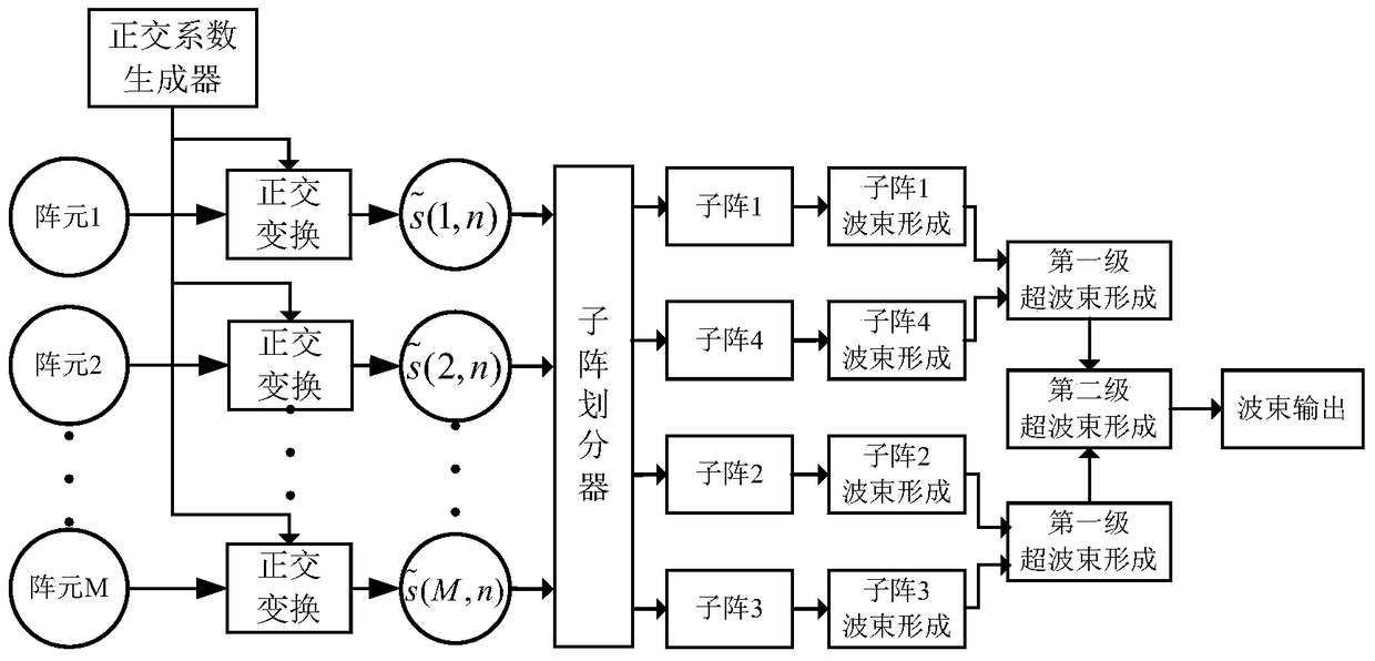
[0039] A multi-beam sounding sonar multi-subarray beam sharpening method comprises the following steps:

[0040] Step (1): performing orthogonal transformation on the original signal received by the transducer array to obtain the required analytical signal;

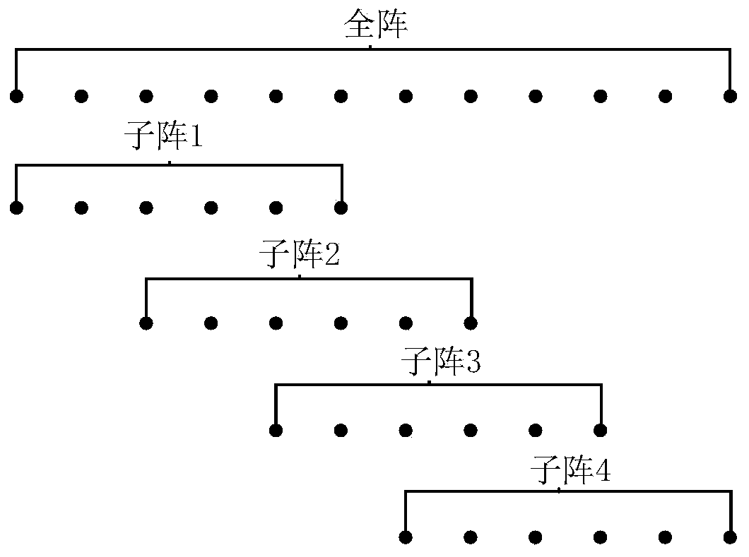
[0041] Step (2): Utilize the subarray divider to divide the obtained analytical signal into subarrays, divide the signal into 4 subarrays with a certain overlap in space, and divide the subarrays into 2 subbeam groups;

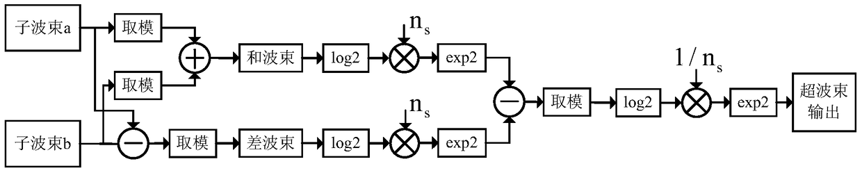
[0042] Step (3): Perform conventional beamforming on each subarray, and perform first-level sharpening beamforming on subbeam group A composed of subarray 1 and subarray 4 and subbeam group B composed of subarray 2 and subarray 3;

[0043] Step (4): The sharpened beamformed output of sub-beam group A and sub-beam group B is used as the input of the next level of sharpened beamforming, and the second leve...


PUM


Abstract

The invention relates to a multibeam depth measuring sonar multi-subarray wave beam sharpening method. The method comprises the following steps: carrying out orthogonal transformation on original signals received by a transducer array to obtain needed parsing signals; by use of a subarray divider, carrying out subarray division on the obtained parsing signals to divide the signals into four subarrays overlapped in space and divide the subarrays into two sub wave beam groups; carrying out routine wave beam formation on each subarray, and respectively carrying out first-order sharpening wave beam formation on a sub wave beam group A formed by the first subarray and the fourth subarray and a sub wave beam group B formed by the second subarray and the third subarray; and taking output generated after sharpening wave beam formation of the sub wave beam group A and the sub wave beam group B as input of next-order sharpening wave beam formation, carrying out a second-order sharpening wave beam formation, and taking output after the second-order sharpening wave beam formation as sharpening multibeam output. According to the invention, a tunnel effect can be inhibited under the condition of a quite small computation amount.

Description

technical field [0001] The invention relates to a multi-beam sounding sonar multi-subarray beam sharpening method. Background technique [0002] The conventional beamformer can enhance the echo signal in the specified direction of arrival and suppress the noise. The principle is simple and the algorithm is easy to implement, so it has been widely used in multi-beam sonar. However, the beamformer has the disadvantages of wide main lobe beam, high side lobe level, and energy leakage, which is easy to cause side lobe interference. The detection target of multi-beam bathymetric sonar is a large area of ​​the seabed. The vertically incident seabed echo beam has strong energy. After the energy leaks into the main lobe direction of other beams, it is easy to form sidelobe interference. This effect is more obvious when the measured seabed is relatively flat and hard, or when the spatial orientation is relatively close. When using seabed detection algorithms such as time-weighted a...

Claims


Application Information

Patent Timeline
Patent Type & Authority Patents(China)
IPC IPC(8): G01S7/52G01S7/539
CPCG01S7/52G01S7/52003G01S7/539
Inventor 李海森魏波周天陈宝伟杜伟东沈嘉俊
Owner HARBIN ENG UNIV
Why Eureka
Try Eureka