
Constant speed control method and apparatus for hydraulic retarder based on fuzzy controls

A hydraulic retarder and fuzzy control technology, applied in the field of vehicles, can solve the problems of high life expectancy, unsatisfactory effect, and the controller cannot give the filling rate, etc., to ensure the safety of vehicles.

Inactive Publication Date: 2015-11-11
JILIN UNIV
View PDF5 Cites 12 Cited by
  • Summary
  • Abstract
  • Description
  • Claims
  • Application Information

AI Technical Summary

Problems solved by technology

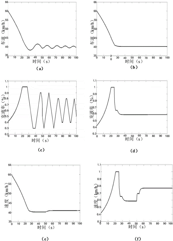
[0003] However, the step-by-step control strategy has disadvantages: there is no constant speed control strategy, and the braking torque can only be adjusted manually by the driver. Although the hydraulic retarder shares part of the performance of the service brake during the downhill process, the effect is not good. not ideal
Disadvantages of the continuously iterative constant speed control strategy: due to the continuous iteration of the controller during the constant speed process, once the driver turns on the constant speed switch, the actual speed of the vehicle will always fluctuate around the target speed and be in a state of continuous adjustment. The retarder cannot give an ideal filling rate, which will make the vehicle go downhill at a constant speed for a long time, and the continuous adjustment of the filling rate has high requirements on the life of the retarder filling rate control valve, which increases the use of cost

Method used


Image

  • Constant speed control method and apparatus for hydraulic retarder based on fuzzy controls
  • Constant speed control method and apparatus for hydraulic retarder based on fuzzy controls
  • Constant speed control method and apparatus for hydraulic retarder based on fuzzy controls

Examples


Embodiment Construction

[0035] Embodiments of the present invention are described in detail below, examples of which are shown in the drawings, wherein the same or similar reference numerals designate the same or similar elements or elements having the same or similar functions throughout. The embodiments described below by referring to the figures are exemplary and are intended to explain the present invention and should not be construed as limiting the present invention.

[0036]In addition, the terms "first" and "second" are used for descriptive purposes only, and cannot be interpreted as indicating or implying relative importance or implicitly specifying the quantity of indicated technical features. Thus, a feature defined as "first" and "second" may explicitly or implicitly include one or more of these features. In the description of the present invention, "plurality" means two or more, unless otherwise specifically defined.

[0037] In the present invention, unless otherwise clearly specified ...


PUM


Abstract

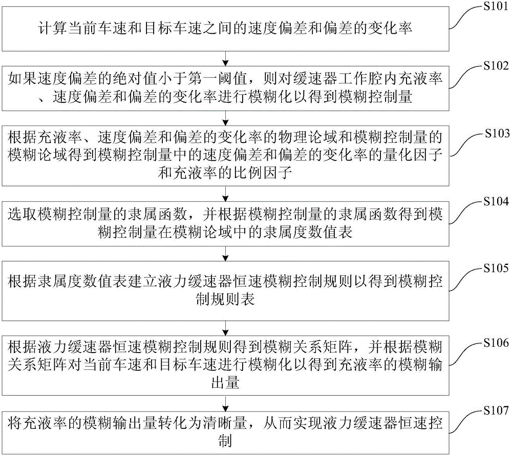
The invention discloses a constant speed control method and a constant speed control apparatus for a hydraulic retarder based on fuzzy controls. The method comprises following steps of calculating speed deviation and speed changing rate. If the speed deviation is less than a set value, then fuzzy process is conducted to the fluid filling rate, the speed deviation and speed changing rate so as to obtain a fuzzy control quantity. According to physics theory and fuzzy theory, quantification factors of the speed deviation and the speed changing rate and a scale factor of the fluid filling rate in the fuzzy control quantity are obtained]. Select membership function and obtain membership grade value table. A membership function is selected and a membership value table is obtained. Control rules are created to obtain a control rule table. According to the control rules, a fuzzy relation matrix is formed and a fuzzy process is conducted to the current speed and the targeted speed of a vehicle so as to obtain a fuzzy output quantity. The fuzzy output quantity is then converted to clear quantity. According to the embodiments of the method, under complicated road traffic condition, a hydraulic retarder is capable of automatically outputting required fluid filling rate and brake torque so as to make a vehicle travel at a constant speed. In this manner, a constant speed control can be realized to the hydraulic retarder to ensure the safe travel of the vehicle.

Description

technical field [0001] The invention relates to the technical field of vehicles, in particular to a method and device for controlling a constant speed of a hydraulic retarder based on fuzzy control. Background technique [0002] In related technologies, for example, there is a step-by-step control strategy: the retarder is divided into 4 gears according to the different filling rates: 100%, 75%, 50% and 25%, and different gears correspond to different braking torques , the driver can select the required gear for braking according to the driving road conditions; for example, the continuous iterative constant speed control strategy: by increasing or decreasing the fixed amount of fluid filling rate (10%) per unit time to maintain the vehicle at a constant speed, When the constant speed switch is turned on, the controller judges the vehicle speed: when the actual vehicle speed is greater than the target vehicle speed, the retarder will automatically increase the filling rate by...

Claims


Application Information

Patent Timeline
IPC IPC(8): G05B13/02G05D13/62
Inventor 雷雨龙宋鹏翔郑宏鹏刘宗晟张元侠刘科扈建龙汤辉林立峰
Owner JILIN UNIV
Learn More