Display panel and driving method thereof, display device

A technology of display panel and driving method, which is applied to static indicators, cathode ray tube indicators, instruments, etc., can solve the problems of mutual interference of display modes and achieve good display effect

Inactive Publication Date: 2015-11-11
BOE TECH GRP CO LTD
View PDF8 Cites 11 Cited by
  • Summary
  • Abstract
  • Description
  • Claims
  • Application Information

AI Technical Summary

Problems solved by technology

[0004] The present invention aims at the problem that the two display modes interfere with each other in the existing semi-reflective and semi-transparent display devices, and provides a display panel capable of achieving good effects in both display modes, a driving method thereof, and a display device

Method used


Image

  • Display panel and driving method thereof, display device
  • Display panel and driving method thereof, display device
  • Display panel and driving method thereof, display device

Examples


Embodiment 1

[0032] This embodiment provides a display panel, which includes:

[0033] Multiple reflective pixels for display using reflected light;

[0034] A plurality of self-displaying pixels that display using transmitted light or self-emission.

[0035] The display panel of this embodiment includes reflective pixels and self-display pixels that are independent of each other, so that when the ambient light is strong, only the reflective pixels can be used for display, while the self-display pixels are black and play the role of a black matrix. When the ambient light is weak, only the self-display pixels are used for display, while the reflective pixels are black and play the role of a black matrix; thus, the two types of pixels are used for display in different situations, and no Mutual interference, the display effect is good.

Embodiment 2

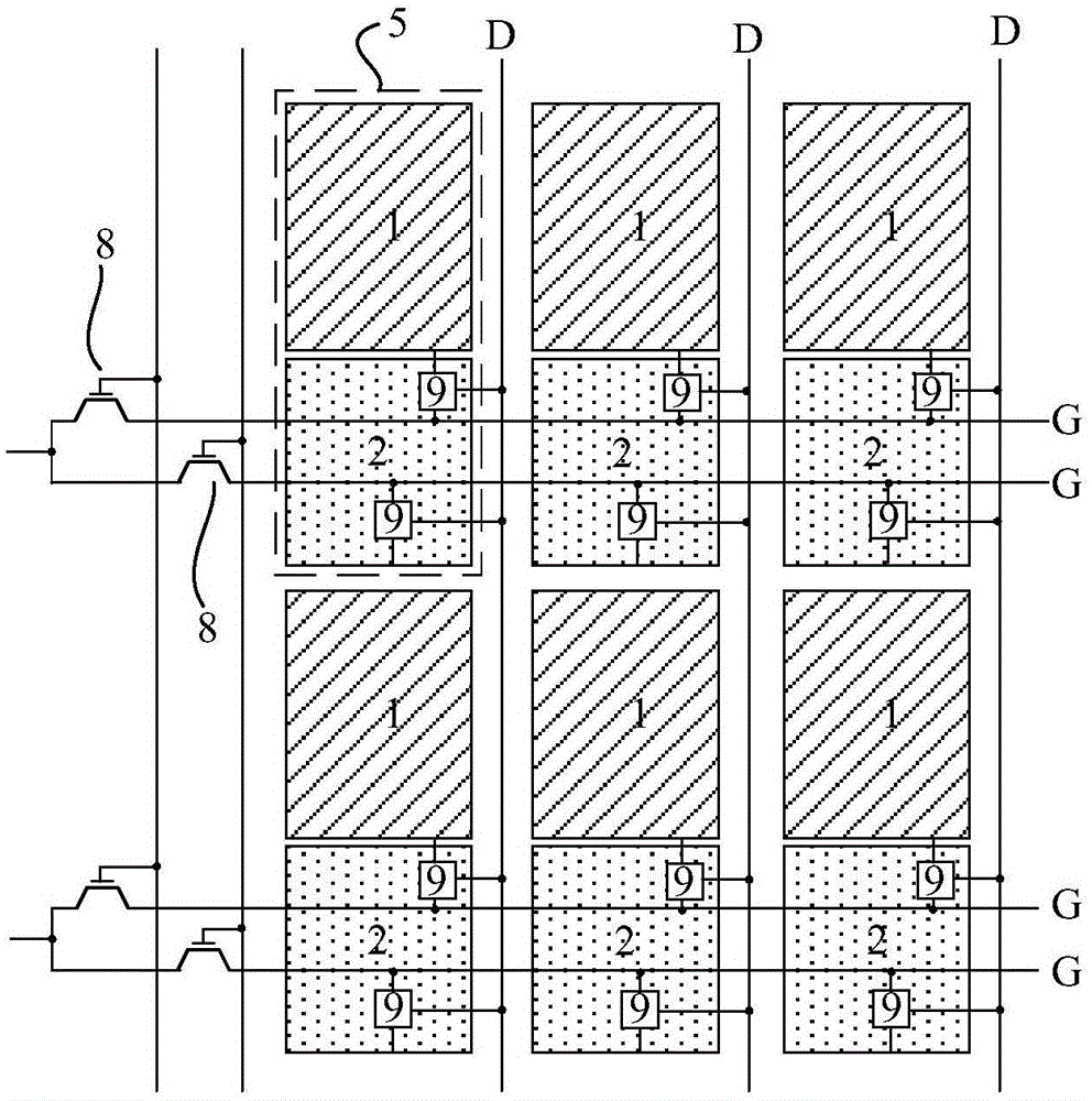
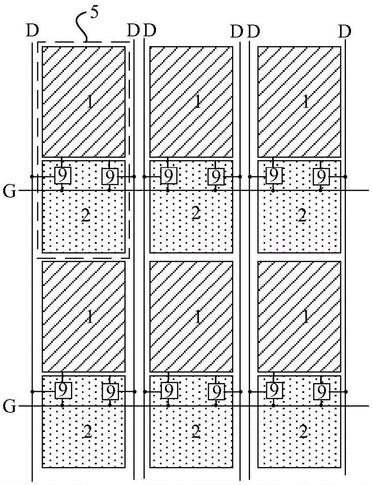
[0037] Such as figure 1 , figure 2 As shown, this embodiment provides a display panel, which includes:

[0038] A plurality of reflective pixels 2 for displaying by reflected light;

[0039] A plurality of self-display pixels 1 that display by transmitted light or self-luminescence.

[0040] And the display panel includes a plurality of display units 5 , and each display unit 5 includes a reflective pixel 2 and a self-display pixel 1 adjacent to the reflective pixel 2 .

[0041] That is to say, the self-display pixel 1 and reflective pixel 2 in the display panel are arranged in "pairs (display unit 5)", and each display unit 5 includes one self-display pixel 1 and one reflective pixel 2 arranged together. , they work together as a "dot" on the display panel that can be displayed independently, and depending on the brightness of the ambient light, one of the two always displays the desired content, and the other displays black as a black matrix. Therefore, the number of se...

Embodiment 3

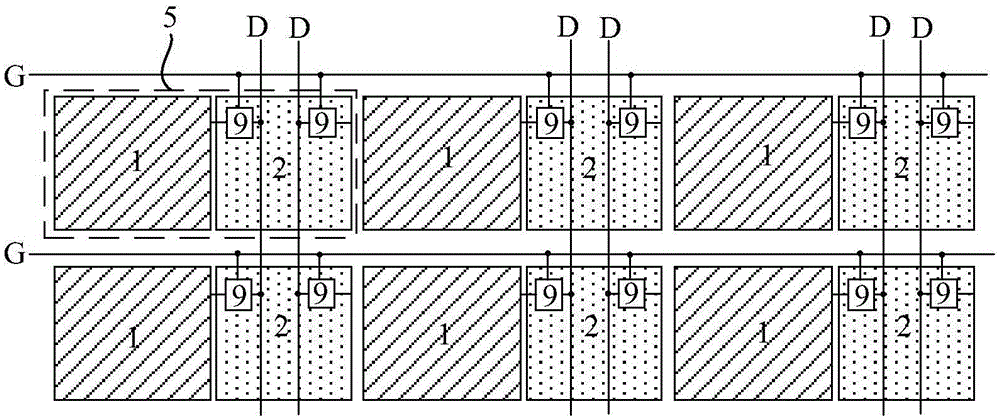
[0065] Such as image 3 As shown, this embodiment provides a display panel, which has a structure similar to that of the display panel in Embodiment 2.

[0066] The difference between the two is that in the display panel of this embodiment, the self-display pixels 1 and reflective pixels 2 in each display unit 5 are arranged adjacently along the row direction; the self-display pixels 1 and reflective pixels 2 in the same row are arranged at intervals, The self-display pixels 1 in any two adjacent rows are arranged adjacently, and the reflective pixels 2 are arranged adjacently.

[0067] That is, if image 3 As shown, the arrangement form of the two kinds of pixels in the display unit 5 of the display panel of this embodiment is opposite to that in Embodiment 2, and is arranged along the row direction; like this, the two kinds of pixels must be arranged at intervals in the row direction, and in In the column direction, the types of pixels in the same column are the same.

[...


PUM


Abstract

The invention provides a display panel and a driving method thereof, and a display device, belonging to the technical field of display. The problem that the two display modes of the existing semi-reflecting and semi-transmitting display device interfere with each other can be solved. The display panel of the invention comprises multiple reflection pixels for display through use of reflected light, and multiple self-display pixels for display through use of transmitted light or self-emitted light.

Description

technical field [0001] The invention belongs to the field of display technology, and in particular relates to a display panel, a driving method thereof, and a display device. Background technique [0002] In existing transflective display devices, each pixel has a part of the area that uses transmitted light or self-illumination for display (self-display, or transmissive display), while the other part of the area reflects the incident ambient light And use it for display (reflective display). The transflective display device adopts the above structure in order to reduce the energy consumption of self-display by using ambient light, and at the same time, it can display reliably by self-display when the ambient light is weak, so that the two display modes can complement each other. [0003] However, in practical applications, it is found that when the ambient light is strong, the effect of reflective display is very good, and there is no need for self-display at all. At this ...

Claims


Application Information

Patent Timeline
Patent Type & Authority Applications(China)
IPC IPC(8): G09G3/34G09G3/36G09G3/38G09G3/30
CPCG09G3/20G09G2300/08G09G2310/02G09G2310/0267G09G2300/0404G09G2300/0426G09G2300/0456G09G2360/144G09G3/38G09G3/2092G09G3/3208G09G3/3453G09G3/3607G09G5/10
Inventor 李文波
Owner BOE TECH GRP CO LTD
Why Eureka
Try Eureka