Large view field array detection radar based on light flight time

A time-of-flight and radar detection technology, which is applied in measuring devices, electromagnetic wave re-radiation, radio wave measurement systems, etc., can solve the problems that mutual interference cannot replace laser radar, etc., and achieve improved light utilization, uniform illumination, and fast detection speed Effect

Pending Publication Date: 2019-03-29
HANGZHOU LANXIN TECH CO LTD
View PDF0 Cites 10 Cited by
  • Summary
  • Abstract
  • Description
  • Claims
  • Application Information

AI Technical Summary

Problems solved by technology

The TOF camera uses the most direct measurement method for depth imaging, obtains better depth information with the smallest computing resources, and realizes the construction of depth scenes at a higher frame rate. However, due to the limited field of view and the gap between multiple cameras, TOF depth cameras Mutual interference cannot replace lidar

Method used


Image

  • Large view field array detection radar based on light flight time
  • Large view field array detection radar based on light flight time
  • Large view field array detection radar based on light flight time

Examples


Embodiment 1

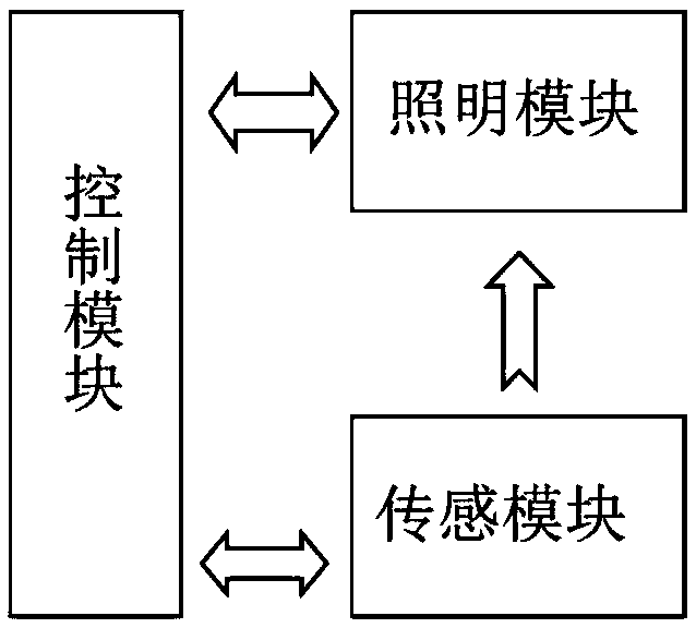
[0048]The large field-of-view area array detection radar based on the time of flight of light provided in this embodiment is an area array radar based on a TOF depth sensor chip, which combines multiple TOF depth sensor chips to perform spatial three-dimensional imaging. Each sensor chip perceives different spatial ranges, and the depth information of different spatial ranges is fused and output at the back end. The radar component modules provided in this embodiment include interconnected lighting modules, sensing modules and control modules. This embodiment The interconnection includes that the control module is connected with the lighting module and the sensing module respectively, and the lighting module is connected with the sensing module; module control, clock synchronization and data transmission are performed; the control module is respectively connected with the lighting module and the sensing module connection, the control module is used to drive the lighting module ...


PUM


Abstract

The invention discloses a large view field array detection radar based on light flight time. The radar comprises an illumination module, a sensing module and a control module; the control module is separately connected with the illumination module and the sensing module; the illumination module transmits light rays outwards according to a preset radiation angle; the sensing module receives a reflective light ray signal according to a preset detection angle; the sensing module inputs the reflection light ray signal to the control module; and the control module is used for controlling the driveof the illumination module and the sensing module, and processing the reflection light ray signal. According to the radar provided by the invention, the different space ranges are radiated by a radiation light source, the radiation angles of the light sources are mutually remedied, and uniform illumination is achieved; multiple light flight time sensing chips are connected in series, and multipledepth sensing chips are used for simultaneously sensing scenes, so that the sensing speed of the large view field array detection radar is significantly higher than that of the scanning type laser radar, and the vibration sensitivity and waste of scanning time of the mechanical scanning type detection are avoided; the problems of limitations on the detection angle of the single-sensor system lensand on the multi-line laser radar detection speed are solved.

Description

technical field [0001] The invention relates to the technical field of area array detection radar, in particular to a large field of view area array detection radar based on a plurality of optical time-of-flight depth sensing chips. Background technique [0002] In recent years, lidar has been more and more used in the fields of atmospheric wind field monitoring, 3D visual imaging, imaging guidance and target tracking. Because lidar has the advantages of high precision and high resolution, after the emergence of unmanned driving technology, it directly drives a group of companies to carry out various lidar research and development and production. However, at present, the cost of LiDAR technology is generally high, and the feedback frame rate is low, so some applications are still in the laboratory stage. Since the operating speed and the scene are different from those of outdoor unmanned vehicles, indoor mobile robots usually require lidar with a higher frame rate and a sho...

Claims


Application Information

Patent Timeline
Patent Type & Authority Applications(China)
IPC IPC(8): G01S17/89G01S7/48G01S7/481
CPCG01S17/89G01S7/4804G01S7/481
Inventor 徐永奎刘志冬齐伟
Owner HANGZHOU LANXIN TECH CO LTD
Why Eureka
Try Eureka