Large high-strength vibration isolating device

A high-strength, large-scale technology, applied in building types, non-rotational vibration suppression, construction, etc., can solve the problem that performance indicators cannot be greatly changed, the bearing capacity stiffness and horizontal deformation capacity of the isolation device are limited, and the pull-out resistance is limited. minor issues

Inactive Publication Date: 2003-12-31
MITSUBISHI HEAVY IND LTD +2
View PDF0 Cites 10 Cited by
  • Summary
  • Abstract
  • Description
  • Claims
  • Application Information

AI Technical Summary

Problems solved by technology

[0003] However, in the conventional seismic isolation device, the pull-out resistance to restrain the upward displacement of the building is relatively small, and the adjustment of the bearing capacity, the stiffness and the horizontal deformation capacity of each unit of the seismic isolation device are relatively limited. of
Moreover, since these performance indicators are interrelated, a single performance indicator cannot be greatly changed

Method used


Image

  • Large high-strength vibration isolating device
  • Large high-strength vibration isolating device
  • Large high-strength vibration isolating device

Examples


Embodiment Construction

[0017] Hereinafter, an embodiment of the present invention will be described with reference to the drawings.

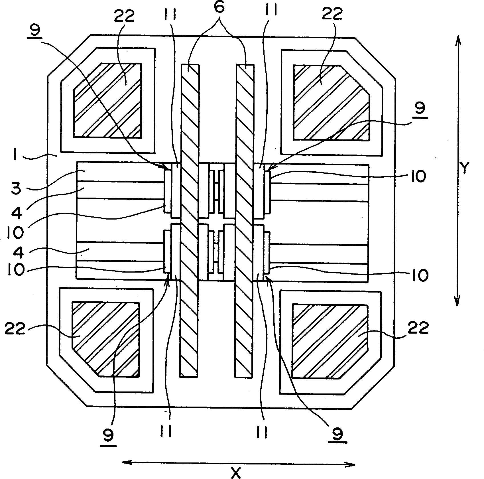
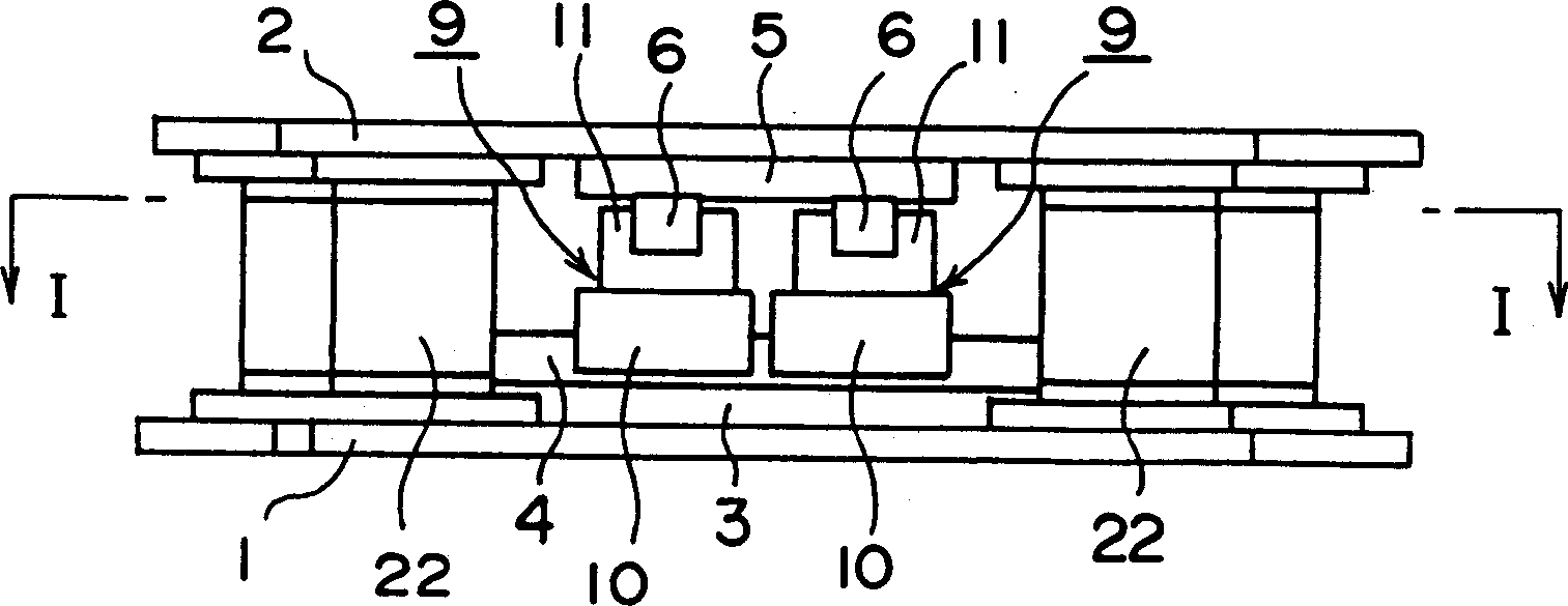
[0018] figure 1 is along figure 2 I-I in is a cross-sectional plan view obtained by looking at an embodiment of the present invention. figure 2 yes figure 1 A front view of . An upper plate 2 is placed on top of a lower plate 1, both of which are flat and have substantially the same shape. In the embodiment shown in the figures, both the lower plate 1 and the upper plate 2 are octagonal, but they can also be made square or circular.

[0019] Two lower guide rails 4 are installed parallel to each other on the upper surface of the lower plate 1 along the transverse direction of the figure through a lower guide rail adapter plate 3 . Although two lower guide rails 4 are installed in the embodiment given in the figure, three or more lower guide rails can also be installed, and only one lower guide rail 4 can be installed so that it passes through the lower plate 1 ...


PUM


Abstract

A seismic isolator includes a lower guide rail having grooves on the side surfaces thereof and fitted to an upper surface of a lower plate, an upper guide rail having grooves on the side surfaces thereof and fitted to a lower surface of an upper plate in a direction criss-crossing the lower guide rail, a block body clamping at its lower part of the lower guide rail and clamping at its upper part of the upper guide rail, a large number of rollers interposed between the lower guide rail and the block body and between the upper guide rail and the block body, a large number of balls interposed between grooves of the side surfaces of the lower guide rail and the block body and between grooves of the side surfaces of the upper guide rail and the block body and a flexible member fitted between the lower surface of the upper plate and the upper surface of the lower plate.

Description

technical field [0001] The present invention relates to an isolator for protecting structures such as buildings from vibrations such as earthquakes. Background technique [0002] Conventional seismic isolation devices generally place some flexible components between the foundation and the building, and, in addition to these flexible components, vibration damping devices and building restoration devices are also provided. [0003] However, in the conventional seismic isolation device, the pull-out resistance to restrain the upward displacement of the building is relatively small, and the adjustment of the bearing capacity, the stiffness and the horizontal deformation capacity of each unit of the seismic isolation device are relatively limited. of. Moreover, since these performance indicators are mutually influenced, a single performance indicator cannot be changed substantially. Contents of the invention [0004] The purpose of the present invention is to propose a shock-...

Claims


Application Information

Patent Timeline
IPC IPC(8): E02D27/34E04H9/02F16F15/04
CPCE02D27/34E04H9/023E04H9/021
Inventor 仓林浩小见俊夫矢口大辅村井信义内山义英山本雅史佐野友治吉冈宏和白井武树道冈英一木本政志
Owner MITSUBISHI HEAVY IND LTD
Why Eureka
Try Eureka