
Passive mechanical circulating pressure release executing device

A technology of release execution and mechanical circulation, applied in valve operation/release device, valve device, mechanical equipment, etc., can solve the problems of high cost, low reliability, operator safety threat, etc., and achieve reliable mechanical action, Low cost and low maintenance cost

Active Publication Date: 2017-12-01
东莞力嘉塑料制品有限公司
View PDF6 Cites 5 Cited by
  • Summary
  • Abstract
  • Description
  • Claims
  • Application Information

AI Technical Summary

Problems solved by technology

The manual push type, as the name suggests, requires personnel to manually open the valve to release the pressure. This method is the most primitive and reliable in operation. However, if the substances contained in the pressure storage container are toxic and harmful, the method of manually opening the valve to release the pressure will be harmful. It poses a safety threat to the operator. In addition, if the pressure release needs to be released periodically and repeatedly, it is necessary to arrange full-time personnel to open the pressure valve regularly, which consumes a lot of labor costs; and the electric control type can realize unattended automatic pressure release. , but the executive mechanism of the electric control method is often more complicated, including control circuits, pressure sensors and other electrical components with high cost. "In some environments where there is no electric energy or it is not suitable to arrange electric energy input (high temperature, high pressure, humidity and other harsh environments), the reliability of "active actuators" such as electric control is not high.

Method used


Image

  • Passive mechanical circulating pressure release executing device
  • Passive mechanical circulating pressure release executing device
  • Passive mechanical circulating pressure release executing device

Examples


Embodiment Construction

[0051] The present invention will be further described below according to the accompanying drawings and specific embodiments, but the embodiments of the present invention are not limited thereto.

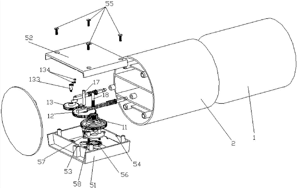
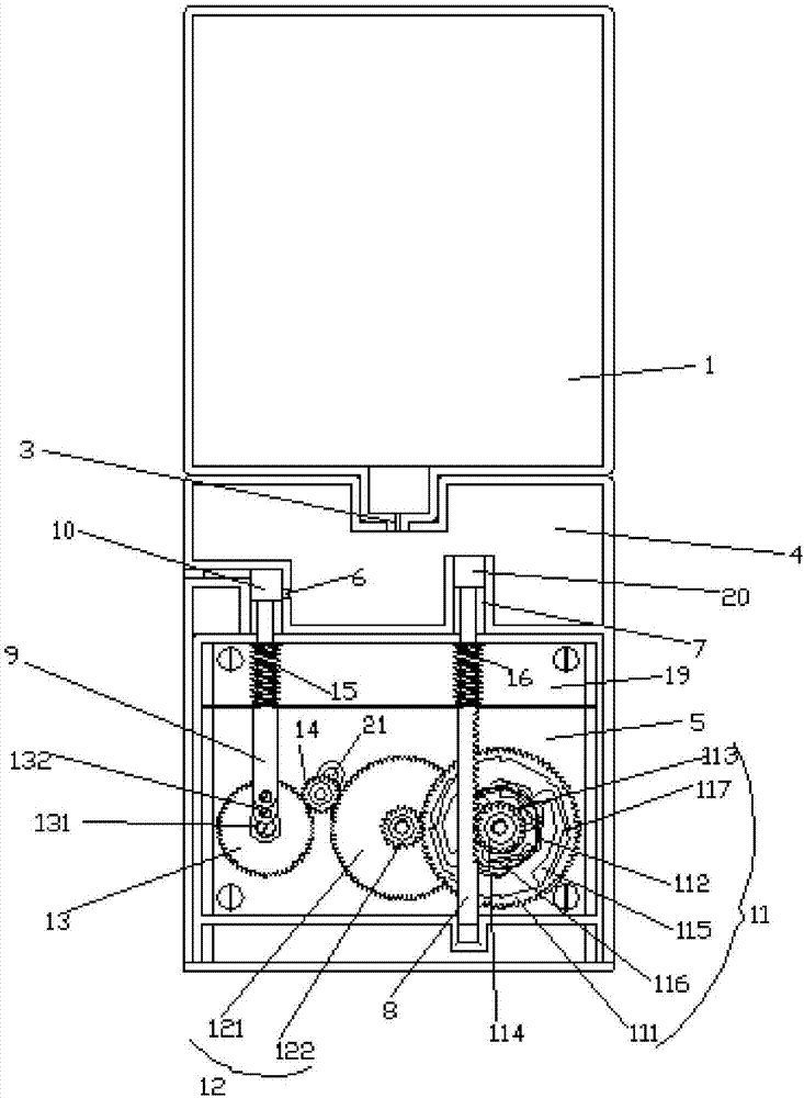
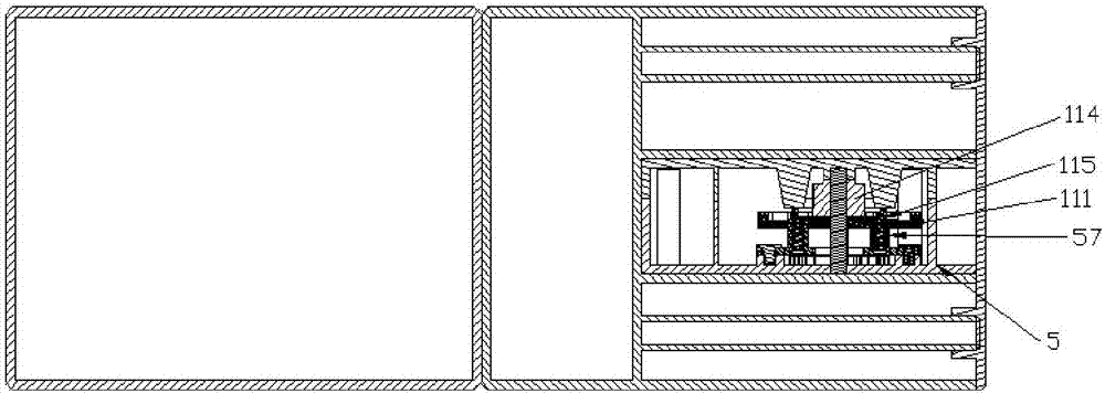
[0052] Such as figure 1 , figure 2 and image 3 As shown, a passive mechanical cycle pressure release actuator includes an upper casing 1 and a pressure storage container 2, the upper casing 1 and the pressure storage container 2 communicate through an air passage 3, and the pressure storage container 2 is provided with a pressure storage cavity 4 and the pressure release gear box 5, the pressure storage cavity 4 has a pressure outlet 6 and a piston mounting hole 7, the pressure release gear box 5 is provided with a linkage reset transmission mechanism, and the linkage reset transmission mechanism is connected to the piston installation hole 7 through the rack 8 ( That is, the piston mechanism), the linkage reset transmission mechanism is connected to a hole plug 10 (that is, the...


PUM


Abstract

The invention discloses a passive mechanical circulating pressure release executing device. The passive mechanical circulating pressure release executing device comprises an upper housing and a pressure storage container. The upper housing communicates with the pressure storage container through an air duct, a pressure storage chamber and a pressure release gear box are arranged in the pressure storage container, the pressure storage chamber is provided with a pressure outlet and a piston mounting hole, a linkage reset transmission mechanism is arranged in the pressure release gear box, the linkage reset transmission mechanism is in butt joint to the piston mounting hole through a valve rod spring, and the linkage reset transmission mechanism is connected to a hole plug through the valve rod. The passive mechanical circulating pressure release executing device achieves functions of pressure relief and resetting by means of the valve rod spring, a rack spring and the linkage reset transmission mechanism, and a transmission force of an air pressure is pulled outward to the farthest stroke by means of a transmission relationship between an output rack pinion and a gear group, so that the pressure outlet is opened to achieve a purpose of quick deflation.

Description

technical field [0001] The invention relates to pressure relief equipment, in particular to a passive mechanical circulation type pressure relief actuator. Background technique [0002] To release the pressure from the pressure storage container, the most critical step is to open the valve of the pressure storage container, and there are many ways to perform this action, such as manual pressing, electric control, etc. The manual push type, as the name suggests, requires personnel to manually open the valve to release the pressure. This method is the most primitive and reliable in operation. However, if the substances contained in the pressure storage container are toxic and harmful, the method of manually opening the valve to release the pressure will be harmful. It poses a safety threat to the operator. In addition, if the pressure release needs to be released periodically and repeatedly, it is necessary to arrange full-time personnel to open the pressure valve regularly, w...

Claims


Application Information

Patent Timeline
Patent Type & Authority Applications(China)
IPC IPC(8): F16K31/122F16K31/48F16K31/54F16K31/52
CPCF16K31/1221F16K31/485F16K31/523F16K31/54
Inventor 李剑威叶德全韩超陈汉雄
Owner 东莞力嘉塑料制品有限公司
Learn More