Air pressure type pipeline connector

A kind of pipe connection, pneumatic technology, applied in the direction of pipe/pipe joint/pipe fitting, connection with fluid pressure for packing and sealing, sleeve/socket connection, etc. Tightness and watertightness, slippery teeth damage and other issues, to achieve good airtightness and watertightness, quick disassembly, convenient assembly and disassembly.

Inactive Publication Date: 2015-08-19
哈尔滨农垦方大管业有限公司
View PDF5 Cites 7 Cited by
  • Summary
  • Abstract
  • Description
  • Claims
  • Application Information

AI Technical Summary

Problems solved by technology

[0002] The pipe connector is a device for splicing two pipes together. In order to ensure the airtight and watertight connection of the pipeline, it is often necessary to increase the compression force of the pipe connector on the two pipes. At present, the commonly used structures are generally screwed structures or elastic joints. Although the buckle structure and the screw structure have shock resistance and relatively stable air and water tightness, when they are used in occasions that require frequent assembly and disassembly, they are prone to slipping and damage, which reduces air-tightness and water loss; for elasticity The buckle structure, although it has good assembly and disassembly convenience, often displaces and creates gaps after encountering strong vibrations, which greatly reduces air-tightness and water-tightness

Method used


Image

  • Air pressure type pipeline connector
  • Air pressure type pipeline connector

Examples


Embodiment Construction

[0016] Hereinafter, the present invention will be further described with reference to the drawings and specific implementations:

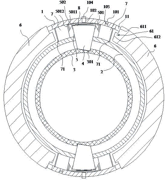
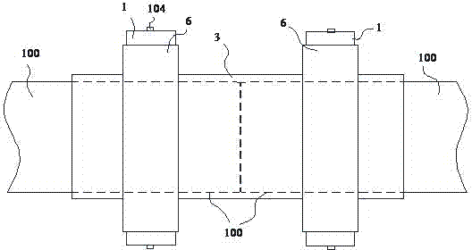
[0017] Such as Figure 1~2 A pneumatic pipe connector shown includes an outer ring 1, a middle ring 2, a movable block 4, a sliding block 6 and a soft rubber inner ring 3, outer ring 1, and middle ring 2 for sealing and sleeved on the outer pipe 100 It is coaxial with the soft rubber inner ring 3 and the inner diameter decreases successively. The outer ring 1 and the middle ring 2 are fixedly connected by a sliding groove 5, and the movable block 4 is built in the sliding groove 5 and is sealed and slidingly fitted with the sliding groove 5 , The inner end of the movable block 4 is elastically connected with the inner wall of the outer ring 1, the soft rubber inner ring 3 is provided with a groove 301 for inserting the outer end of the movable block 4; the groove wall of the sliding groove 5 is provided with a first air inlet channel 501, the first a...


PUM


Abstract

The invention discloses an air pressure type pipeline connector. The air pressure type pipeline connector comprises an outer ring, a middle ring, a movable block, a sliding block and a soft rubber inner ring installed on an external pipeline in a sealing and sleeving mode, wherein the outer ring, the middle ring and the soft rubber inner ring are coaxially arranged, the inner diameter of the outer ring, the inner diameter of the middle ring and the inner diameter of the soft rubber inner ring become smaller in sequence, and the outer ring and the middle ring are fixedly connected through a sliding groove; the movable block is arranged in the sliding groove and is in sliding fit with the sliding groove in a sealing mode, the inner end of the movable block is in elastic connection with the inner wall of the outer ring, and a groove allowing the outer end of the movable block to be inserted therein is formed in the soft rubber inner ring; a first air inlet channel is formed in the wall of the sliding groove, a first one-way air valve allowing air to be introduced into the sliding groove in one direction is arranged in the first air inlet channel, the inner end of the first air inlet channel is communicated with the sliding groove and located between the inner end of the movable block and the inner wall of the outer ring, and the outer end of the first air inlet channel is communicated with an air chamber. By the adoption of the air pressure type pipeline connector, on the basis that convenient detachment is guaranteed, high airtight performance and high watertight performance can be maintained in a vibration environment.

Description

Technical field [0001] The invention relates to a pipe connection device, in particular to a pneumatic pipe connection piece. Background technique [0002] The pipe connector is a device that splices two pipes together. In order to ensure the airtight and watertight connection of the pipe, it is often necessary to increase the pressing force of the pipe connector on the two pipes. At present, the commonly used structure is generally a screw connection structure or elastic Although the buckle structure and the screw connection structure have shock resistance and relatively stable air-tightness and water-tightness, when they are used in occasions that require frequent assembly and disassembly, they are prone to slippage and damage, reducing air-tightness and water trapping; for elasticity Although the buckle structure has better assembly and disassembly convenience, it is often misaligned after encountering strong vibrations, resulting in gaps, which greatly reduces air tightness a...

Claims


Application Information

Patent Timeline
Patent Type & Authority Applications(China)
IPC IPC(8): F16L21/025
CPCF16L17/10
Inventor 谢洁萍
Owner 哈尔滨农垦方大管业有限公司
Why Eureka
Try Eureka