
Watercraft fender

a technology for fenders and watercraft, applied in the field of fenders, can solve the problems of fenders slipping out of place due to wave action, negated protection, further damage, etc., and achieve the effects of quick and easy folding for storage, low pressure inflation and rapid deflation

Active Publication Date: 2010-05-25
KAEMMERLING THOMAS ROBERT
View PDF6 Cites 8 Cited by
  • Summary
  • Abstract
  • Description
  • Claims
  • Application Information

AI Technical Summary

Benefits of technology

"The present invention provides an inflatable, round or nearly round, airtight, waterproof bladder that is placed in a rugged, non-marring covering. This fender can be easily inflated and deflated with a valve, and has straps that can be adjusted to provide optimal protection. The fender can be folded for easy stowage when deflated. The use of this fender does not require any modifications to the watercraft."

Problems solved by technology

Ordinary fenders, due to their inherent size and shape, fall into this gap negating any protection.
If one attempts to place ordinary fenders between the watercraft and the pilings themselves, the fenders tend to roll out of place due to wave action.
Additionally, if the side of the dock is higher than the gunwale, ordinary fenders do not prevent the craft from riding up and under the dock, causing further damage.
Ordinary fenders are bulky, difficult to stow and require multiple units of various sizes to remedy the unlimited variations in dock length, dock height and dock rail-to-hull distance.
They are difficult to adjust, have limited attachment points on the watercraft, are bulky and difficult to stow.
1) The patent has since expired.
2) The bladder of the device is elongated as opposed to round or nearly-round. This shape would permit the bladder to float on its flattest side, reducing the level of protection. The oblong shape also creates an uneven pressure levels on the seams, thus increasing the potential for seam failure.
3) The device is for use on inflatable boats: a limited application.
4) The device requires high inflation pressures. Specialized inflation equipment must be available. There is also and increased danger of seam failure and / or explosion.
1) The device is designed for temporary and / or permanent attachment to the craft and involves modifying the hull of the craft with various mounting devices. As one is altering the hull, there is the possibly of diminishing hull integrity. The device may require professional installation. Permanent installation may impede watercraft performance. Permanent installation detracts from the watercraft's appearance.
2) The device requires the use of heavy and dangerous to stow compressed bottle gas for inflation.
3) The bladder of the device is elongated as opposed to round or nearly-round. This shape would permit the bladder to float on its flattest side, reducing the level of protection. The oblong shape also creates an uneven pressure levels on the seams, thus increasing the potential for seam failure.
4) Due to the mounting method, the height of the bladder is not readily adjustable over the length of the watercraft.
5) Due to the mounting method, the fender cannot be employed on the dock or pier in lieu of the watercraft if the situation warrants.
As one is altering the hull, there is the possibly diminishing hull integrity.
Permanent installation may impede watercraft performance.
This appendage obstructs portability and inhibits ease of use for the recreational boater.
Small, portable tire inflators inflate too slowly for recreational boating use.
High volume tire inflators are bulky, heavy and are not practical to keep aboard the average recreational boat.
4) Due to the ballasted bag assembly, function of the device would be impaired as the height of the bladder would not be adjustable over the length of the watercraft.
5) Due to the mounting method, the fender cannot be employed on the dock or pier in lieu of the watercraft if the situation warrants.

Method used


Image

  • Watercraft fender
  • Watercraft fender
  • Watercraft fender

Examples


Embodiment Construction

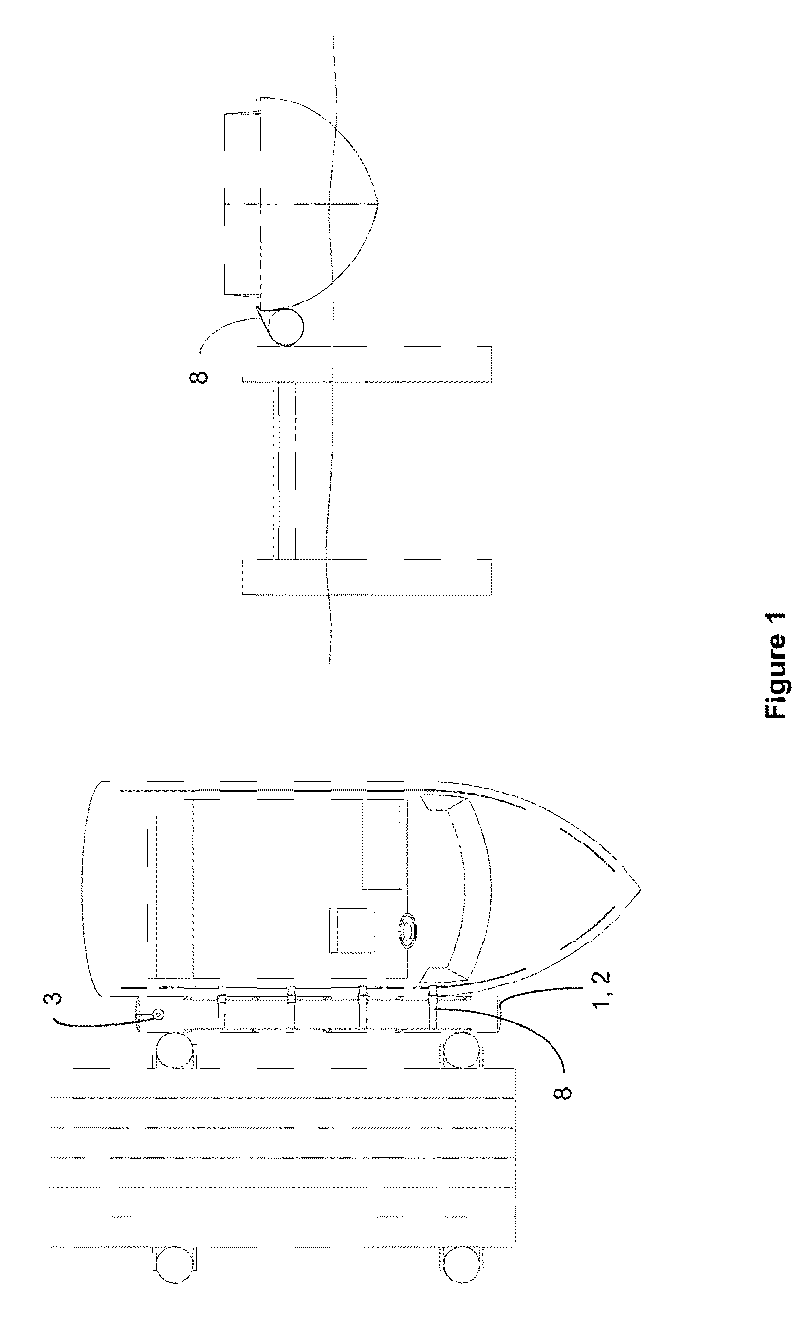
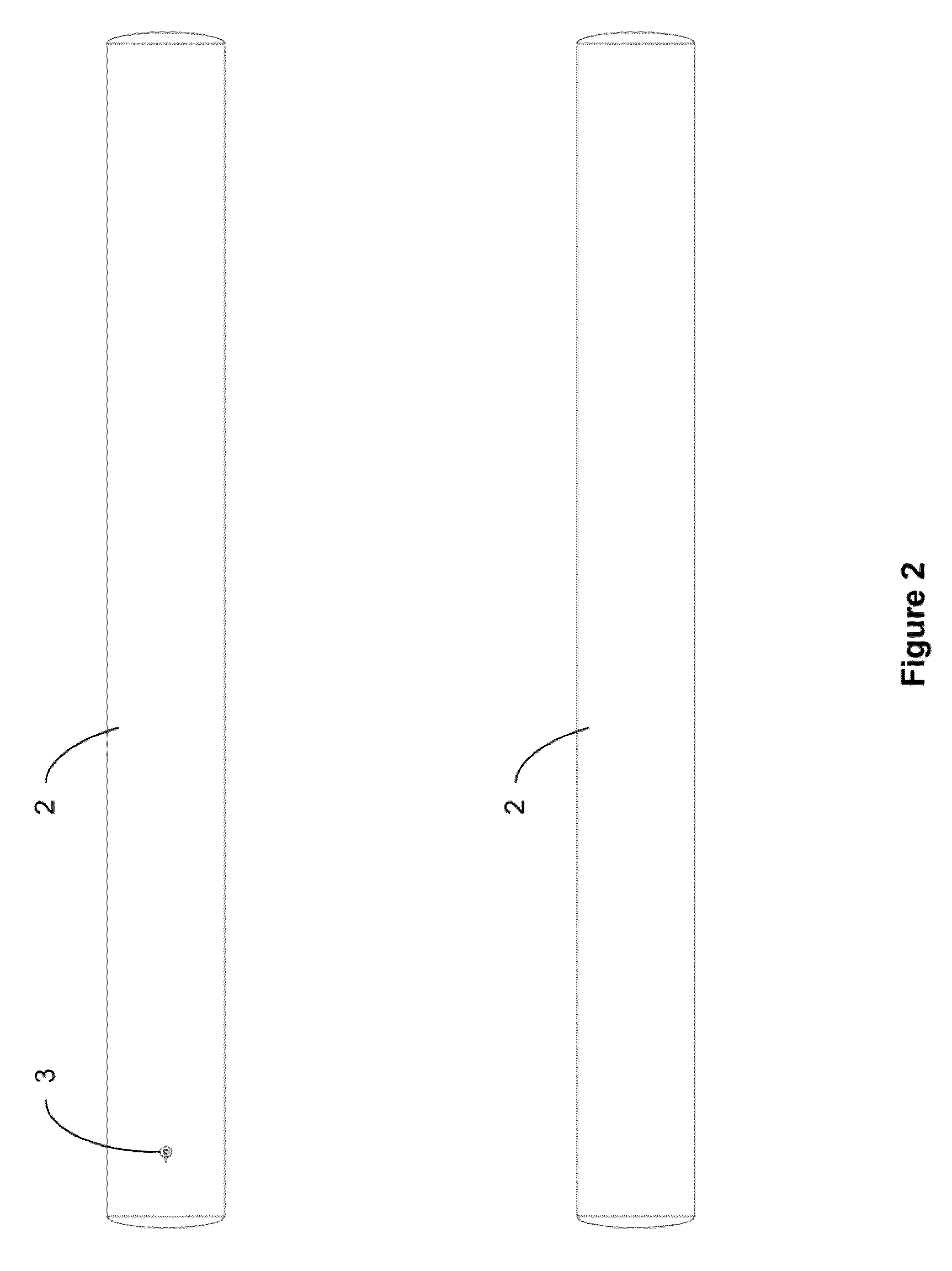
[0048]FIG. 1 is an application view of a boat fender in accordance with the invention. An inflatable bladder (2) resides within a protective cover (1). The cover / bladder assembly is heretofore referred to as “fender”. The length of the fender will vary with the length of the watercraft on which it will be utilized: ideally the length of the longest straight section of the watercraft that is likely to make contact with a dock, pier and / or pilings. Several fenders may be utilized for longer watercraft. The diameter of the fender will also vary with the size of the watercraft. The watercraft does not have to be modified in any manner to utilize the fender.

[0049]In operation, the watercraft is brought alongside the dock or pier to which it is to be moored. The fender is inflated and placed between the watercraft's hull and the dock or pier. If the dock has external pilings, or the rails of the dock or pier are above the gunwale, the watercraft is situated so that the longest straight se...


PUM


Abstract

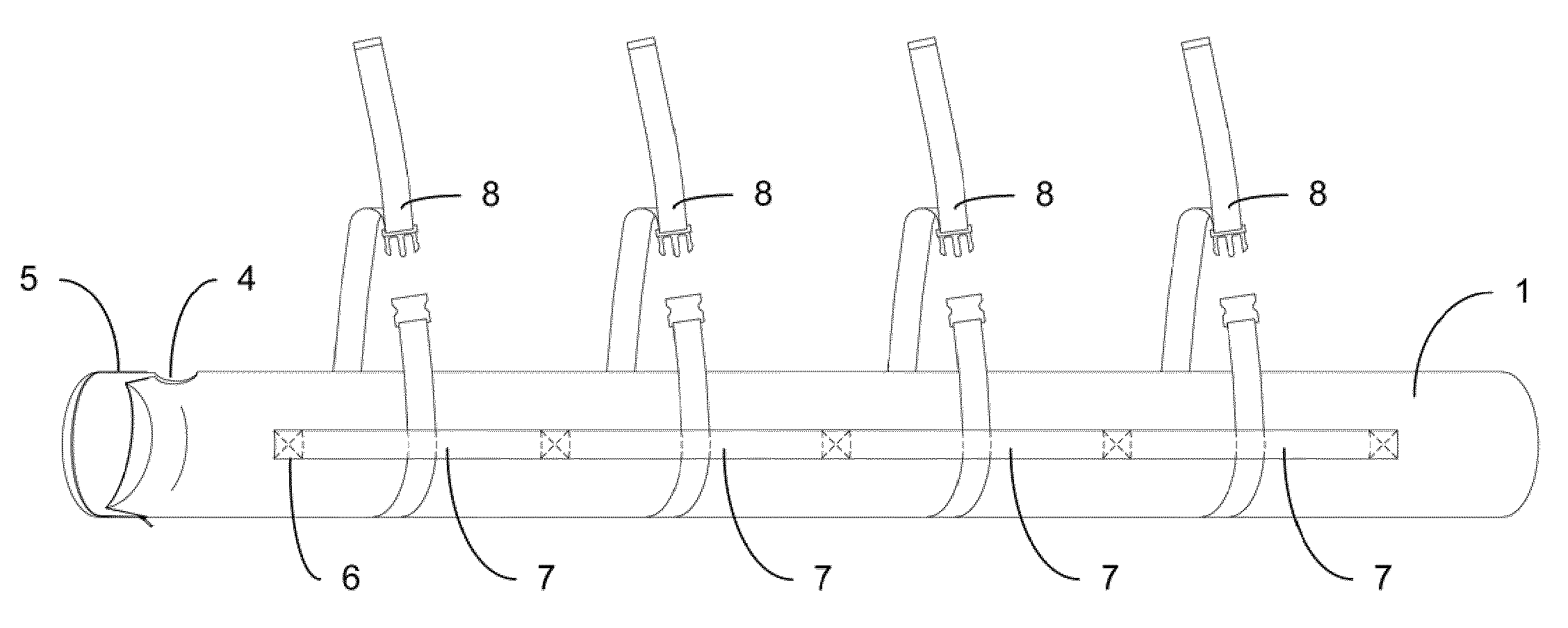
A portable fender for protecting a watercraft hull from damage. The fender(s) length corresponds to the length of the watercraft likely to make contact with a dock, pier and / or pilings. An inflatable, waterproof bladder resides in a protective cover. The bladder's valve permits rapid inflation and deflation. The cover has diametrically opposed straps running its length. These straps are anchored to the cover in such a manner that loops are created at regular intervals. Mooring straps are passed through the loops and around the fender. The fender is secured between the watercraft and the dock / pier / pilings by attaching mooring straps to any convenient point on the watercraft, dock, pier, pilings or other suitable mooring point. Lengthening or shortening each individual mooring strap allows the fender to be placed in a position that will provide optimum protection. The fender is easily deflated for stowage. The watercraft does not have to be modified in any manner to use the fender.

Description

FIELD OF THE INVENTION[0001]The present invention relates to watercraft fenders and, more particularly, to a portable method of watercraft protection from dock abrasion despite differences in dock height or type of dock construction.BACKGROUND OF THE INVENTION[0002]Boat docks come in many styles and sizes. Many incorporate a structural design in which the pilings are located externally to the dock's side rails. When the length of the watercraft exceeds the length between the pilings, the watercraft must be moored against these external pilings. Therefore, a gap is created between the side of the watercraft and the side (rail) of the dock itself. Ordinary fenders, due to their inherent size and shape, fall into this gap negating any protection. If one attempts to place ordinary fenders between the watercraft and the pilings themselves, the fenders tend to roll out of place due to wave action. Additionally, if the side of the dock is higher than the gunwale, ordinary fenders do not pr...

Claims


Application Information

Patent Timeline
Patent Type & Authority Patents(United States)
IPC IPC(8): B63B59/02
CPCB63B59/02B63B2059/025
Inventor KAEMMERLING, THOMAS ROBERT
Owner KAEMMERLING THOMAS ROBERT
Learn More