Cable connection positioning device

A positioning device and cable technology, applied in the direction of cable installation device, cable installation, electrical components, etc., can solve the problems of occupying the inner space of the cabinet, the space is small, and it is difficult to apply pulling force.

Inactive Publication Date: 2015-11-11
唐花女
View PDF5 Cites 7 Cited by
  • Summary
  • Abstract
  • Description
  • Claims
  • Application Information

AI Technical Summary

Problems solved by technology

In the internal space of these cabinets, the components are often arranged compactly and the space is small, which brings difficulties to the wiring work.
[0003] Especially in the case where manual operation is required to pull the cable, since the cable length margin needs to be reserved for the wiring operation, it is easy to cause the

Method used


Image

  • Cable connection positioning device

Examples


Embodiment Construction

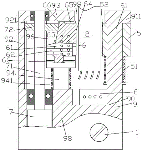
[0008] The following specific examples and joint attachments figure 1 The present invention will be described in detail.

[0009] see figure 1 , according to a cable wiring positioning device of the present invention, used for positioning the terminal of the cable to be electrically connected with the terminal block 8 of the power equipment, the device comprises a base frame 9 and a lower base body 98 fixed on the base frame In the positioning motor 7, the screw rod 71 driven by the positioning motor 7 has an end to be rotatably fixed in the upper beam 93 of the base frame 9, and the screw rod 71 is threaded with the movable wedge 72 to make The left side of the movable wedge 72 is slidably fitted with the guide rail groove 921 of the base frame 9 provided in the longitudinal bracket 92 between the upper beam 93 and the lower base 98 and the movable wedge 72 is in sliding fit. The right wedge surface engages with the inclined surface 63 on the left side of the clamping block...


PUM


Abstract

The invention discloses a cable connection positioning device, which is used for positioning a connection end of a cable for electrical connection with a connection seat (8) of power equipment. The cable connection positioning device comprises a base frame (9) and a positioning motor (7), wherein the positioning motor (7) is fixed in a lower base body (98) of the base frame; a screw rod (71) driven by the positioning motor (7) comprises a tail end for being rotationally fixed in an upper beam (93) of the base frame (9); and the screw rod (71) and a movable wedge block (72) are in screw-thread fit, so that the left side of the movable wedge block (72) and a guide rail groove (921) in a longitudinal bracket (92), arranged between the upper beam (93) and the lower base body (98), of the base frame (9) are in sliding fit, and a wedge surface on right side of the movable wedge block (72) is jointed with the wedge surface (63) on the left side of a clamping block (6).

Description

technical field [0001] The present application relates to the field of power cables, in particular to a cable wiring positioning device. Background technique [0002] In the process of wiring and wiring in the field of power cables, it is often necessary to lead the cables to the inside of the cabinet of power electrical equipment such as electrical cabinets, so as to realize the required connections such as electrical power supply. In the internal space of these cabinets, the devices are often arranged compactly and the space is small, which brings difficulties to the wiring work. [0003] Especially in the case where manual operation is required to pull the cable, because the cable length margin needs to be reserved for the wiring operation, it is easy to occupy the inner space of the cabinet and thus interfere with the normal operation of other electrical devices after the wiring is completed. Moreover, due to the rigidity of the cable itself, it is very difficult to per...

Claims


Application Information

Patent Timeline
IPC IPC(8): H02G1/00
Inventor 唐花女
Owner 唐花女
Why Eureka
Try Eureka