Network interface unit and method for operating network interface unit

A technology of network interface and division unit, applied in the direction of network connection, data exchange network, electrical components, etc., can solve the problems of small flexibility and limited application, and achieve the effect of constant passing time or processing time

Active Publication Date: 2015-11-11
ROBERT BOSCH GMBH
View PDF7 Cites 2 Cited by
  • Summary
  • Abstract
  • Description
  • Claims
  • Application Information

AI Technical Summary

Problems solved by technology

A disadvantage of these known network interface units is their low flexibility and thus limited application

Method used


Image

  • Network interface unit and method for operating network interface unit
  • Network interface unit and method for operating network interface unit
  • Network interface unit and method for operating network interface unit

Examples


Embodiment Construction

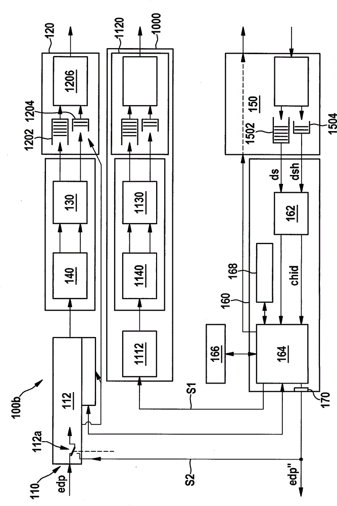
[0025] figure 1 The network interface unit 100 according to the first embodiment is schematically shown. The network interface unit 100 has an input terminal 110 for receiving Ethernet data packets edp, for example Ethernet data packets according to the IEEE802.3 standard.

[0026] In one embodiment, the input terminal 110 is connected eg directly to an Ethernet switch (not shown), preferably via a Serial Gigabit Media Independent Interface (SGMII) type interface. Alternatively, the input terminal 110 can also be connected via an interface of the Reduced Gigabit Media Independent Interface (RGMII) type, for example to an interface operating on the bit transport layer (physical layer) of the ISO / OSI base reference model. In general, the already mentioned Ethernet data packets edp can be supplied to the network interface unit 100 via the input terminal 110 . In one specific embodiment, the input terminal 110 is designed for transmission of the Gigabit Ethernet (GbE) type.

[...


PUM


Abstract

A network interface unit includes: at least one input terminal for receiving Ethernet data packets; at least one output terminal; and a segmentation unit configured for (i) segmenting at least one of a received Ethernet data packet and an Ethernet data packet modified by the network interface unit into at least one data segment having a predefined length, and (ii) for outputting the at least one data segment via the output terminal.

Description

technical field [0001] The invention relates to a network interface unit with at least one input terminal for receiving Ethernet data packets and at least one output terminal. [0002] Furthermore, the invention relates to a method for operating such a network interface unit. Background technique [0003] Network interface units of the type mentioned at the outset are known and are designed, for example, to receive and / or send out so-called Ethernet data packets, that is, network data packets, which in particular comply with the IEEE (Institute of Electrical and Electronics Engineers ) 802.3 standard. In this case, the transmission of the Ethernet data packets takes place in a manner known per se via a medium that may possibly be shared with other network interface units (“shared medium”), in particular via electrical and / or optical data connections. A disadvantage of these known network interface units is their low flexibility and thus limited application. Contents of t...

Claims


Application Information

Patent Timeline
Patent Type & Authority Applications(China)
IPC IPC(8): H04L12/951H04L47/43H04L69/14
CPCH04L69/22H04L12/66H04L47/36H04L69/166
Inventor A.布鲁内H.洛伊韦尔C.波尔
Owner ROBERT BOSCH GMBH
Why Eureka
Try Eureka