Mixing Valve of An Internal Combustion Engine

a technology of internal combustion engine and mixing valve, which is applied in the direction of machines/engines, water supply installation, etc., can solve the problems of high degree of dependence between the movement of the flap, and achieve the effect of keeping the ratio of the flaps particularly low, and reducing the inherent dynamic behavior of the flap

Active Publication Date: 2015-04-23
VITESCO TECH GERMANY GMBH
View PDF3 Cites 2 Cited by
  • Summary
  • Abstract
  • Description
  • Claims
  • Application Information

AI Technical Summary

Benefits of technology

[0014]According to another advantageous development of the invention, the outlay in terms of construction for holding the shaft of the flap of the intake duct can be kept particularly low if a holding element is secured on the shaft of the flap of the intake duct, and if the spring element supports the holding element relative to the housing.
[0015]According to another advantageous development of the invention, the assembly of the mixing valve is particularly simple if the holding element and the control arm are arranged on mutually opposite ends of the shaft of the flap of the intake duct.
[0016]According to another advantageous development of the invention, further reduction of the inherent dynamic behavior of the flaps can be achieved if the shaft of the flap of the exhaust duct is preloaded into a home position by a spring element.

Problems solved by technology

However, this leads to a high degree of dependence between the movements of the flaps.

Method used


Image

  • Mixing Valve of An Internal Combustion Engine
  • Mixing Valve of An Internal Combustion Engine
  • Mixing Valve of An Internal Combustion Engine

Examples


Embodiment Construction

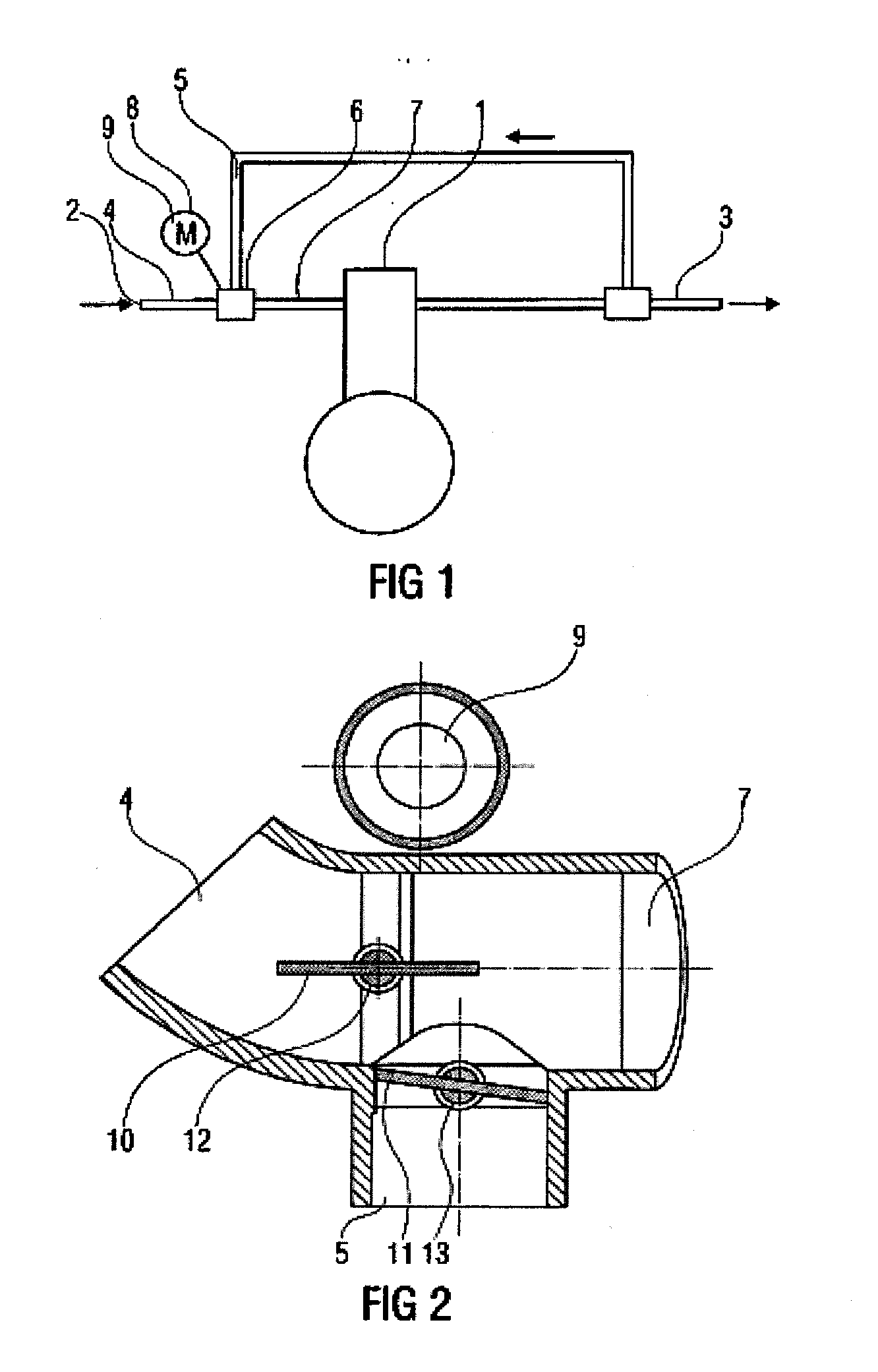
[0023]FIG. 1 shows schematically an internal combustion engine 1 having an intake line 2 and having an exhaust line 3. The intake line 2 has an intake duct 4, via which air from the environment is drawn in. An exhaust duct 5 leads from the exhaust line 3, via a mixing valve 6, into the intake line 2. The mixing valve 6 joins the intake duct 4 and the exhaust duct 5 together to form a combined duct 7. The combined duct 7 leads directly to the internal combustion engine 1. A driving device 8 having an electric servomotor 9 enables the mixing valve 6 to be adjusted.

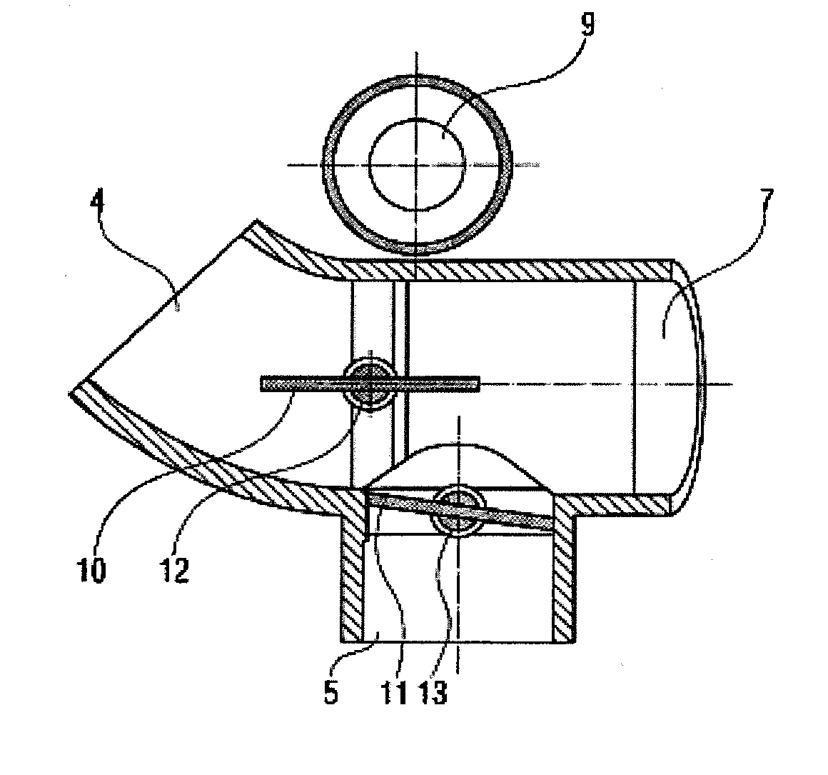
[0024]FIG. 2 shows a sectional view of the mixing valve 6 from FIG. 1. Respective flaps 10, 11 are secured on pivotable shafts 12, 13 in the intake duct 4 and in the exhaust duct 5, respectively. The exhaust duct 5 is arranged at right angles to the intake duct 4 and the combined duct 7. The servomotor 9 is arranged on the opposite side of the combined duct 7 from the exhaust duct 5. In an alternative embodiment, which is no...


PUM


Abstract

A mixing valve of an internal combustion engine of a motor vehicle includes: a flap arranged in a suction channel and a flap arranged in an exhaust gas channel. One single flap of the two flaps is drivable via a gear pair with non-round or eccentric gears. The drive of the other flap has lost motion, whereby the closing movements of the flaps can be formed in a particularly free manner with only a single actuating motor.

Description

CROSS-REFERENCE TO RELATED APPLICATIONS[0001]This is a U.S. national stage of application No. PCT / EP2013 / 058961, filed on 30 Apr. 2013, which claims priority to the European Application No. EP 12464007.9 filed 9 May 2012, the content of both incorporated herein by reference.BACKGROUND OF THE INVENTION[0002]1. Field of the Invention[0003]The invention relates to a mixing valve of an internal combustion engine of a motor vehicle, having a flap arranged in an intake duct and a flap arranged in an exhaust duct, having shafts, which are rotatably mounted in a housing and hold the flaps, wherein the intake duct and the exhaust duct open into a common combined duct, and having a driving device for driving the flaps.[0004]2. Related Art[0005]Mixing valves of this kind are often used in exhaust gas recirculation systems of internal combustion engines of modern motor vehicles and are known in practice. The movements of the flaps of the intake duct and of the exhaust duct are controlled such t...

Claims


Application Information

Patent Timeline
Patent Type & Authority Applications(United States)
IPC IPC(8): F02M25/07F16K1/22F16K31/04F16K11/00F16K11/14
CPCF02M25/0786F16K19/00F16K11/14F16K31/043F02M25/0796F02M25/0773F02M25/0792F02M25/0793F02M25/0798F16K1/22F16K31/535F16K31/041F16H2035/003F16K11/22F02M26/69F02M26/21F02M26/54F02M26/64F02M26/70F02M26/71Y10T137/87692F02M26/51
Inventor MAXIM, DANIEL IOSIF
Owner VITESCO TECH GERMANY GMBH
Why Eureka
Try Eureka