Valve device for a turbine of an exhaust gas turbocharger

a technology of exhaust gas and valve device, which is applied in the direction of valve arrangement, combustion engine, machine/engine, etc., can solve the problems of excessive wear and damage to the valve device, and achieve the effect of keeping wear particularly low, easy and cost-effective, and reducing the risk of damag

Inactive Publication Date: 2015-10-01
DAIMLER AG
View PDF1 Cites 0 Cited by
  • Summary
  • Abstract
  • Description
  • Claims
  • Application Information

AI Technical Summary

Benefits of technology

[0012]The invention provides for valve device for a turbine of an exhaust gas turbocharger, in which loads and wear on the valve device resulting from the actuation of the valve element which is subjected to the hot exhaust gas which is still under pressure can be kept particularly low in an easy and cost-effective manner. The valve element is mounted on at least one second bearing point which is at a distance from the first bearing point so that it can be rotated about the axis of rotation. The at least one second bearing point enables a pivoting of the valve element and in particular of the shaft whereby wear can be kept low.
[0013]As a result, the valve element can be pivoted about the axis of rotation frequently and also over a particularly long life span of the valve device without this leading to excessive wear and resulting damage to the valve device. The arrangement provides for a cost-effective adjustment mechanism of the valve element which ensures variable and as-required matching of the exhaust gas turbocharger to different operating points of an internal combustion engine associated with the exhaust gas turbocharger, even over a long life span.
[0014]The advantageous mounting of the valve element at the at least two bearing points results in low wear of the valve device without using particularly costly materials and / or without having to provide particularly costly machining methods and treatments of components of the valve device. Rather, inexpensive materials can also be used for mounting the valve element, i.e. for example for the shaft and the housing element, while at the same time fulfilling the functional requirements very reliably.

Problems solved by technology

As a result, the valve element can be pivoted about the axis of rotation frequently and also over a particularly long life span of the valve device without this leading to excessive wear and resulting damage to the valve device.

Method used


Image

  • Valve device for a turbine of an exhaust gas turbocharger
  • Valve device for a turbine of an exhaust gas turbocharger

Examples


Embodiment Construction

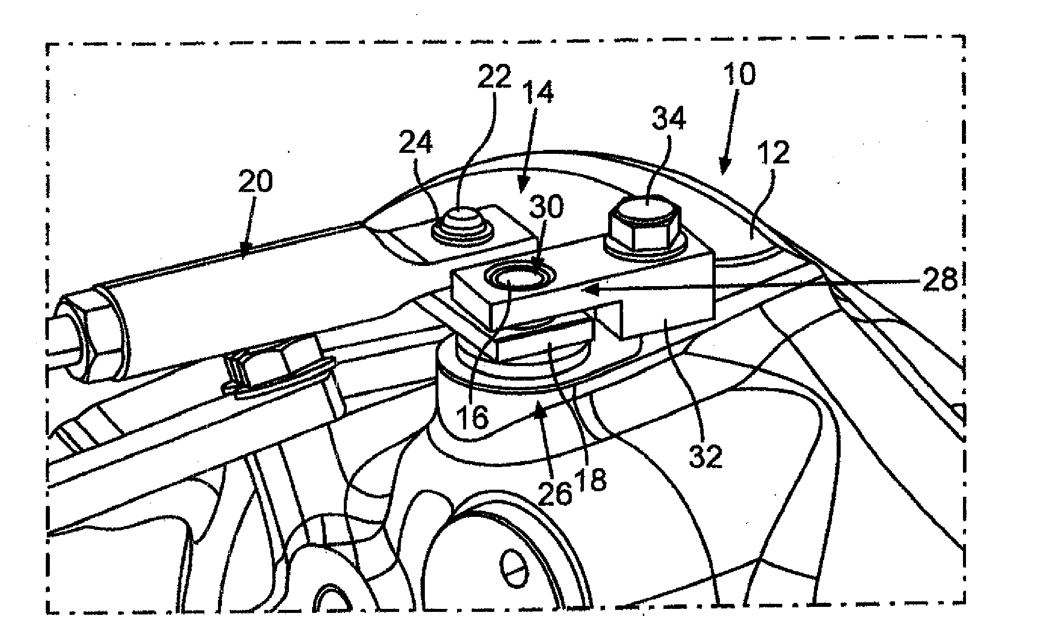
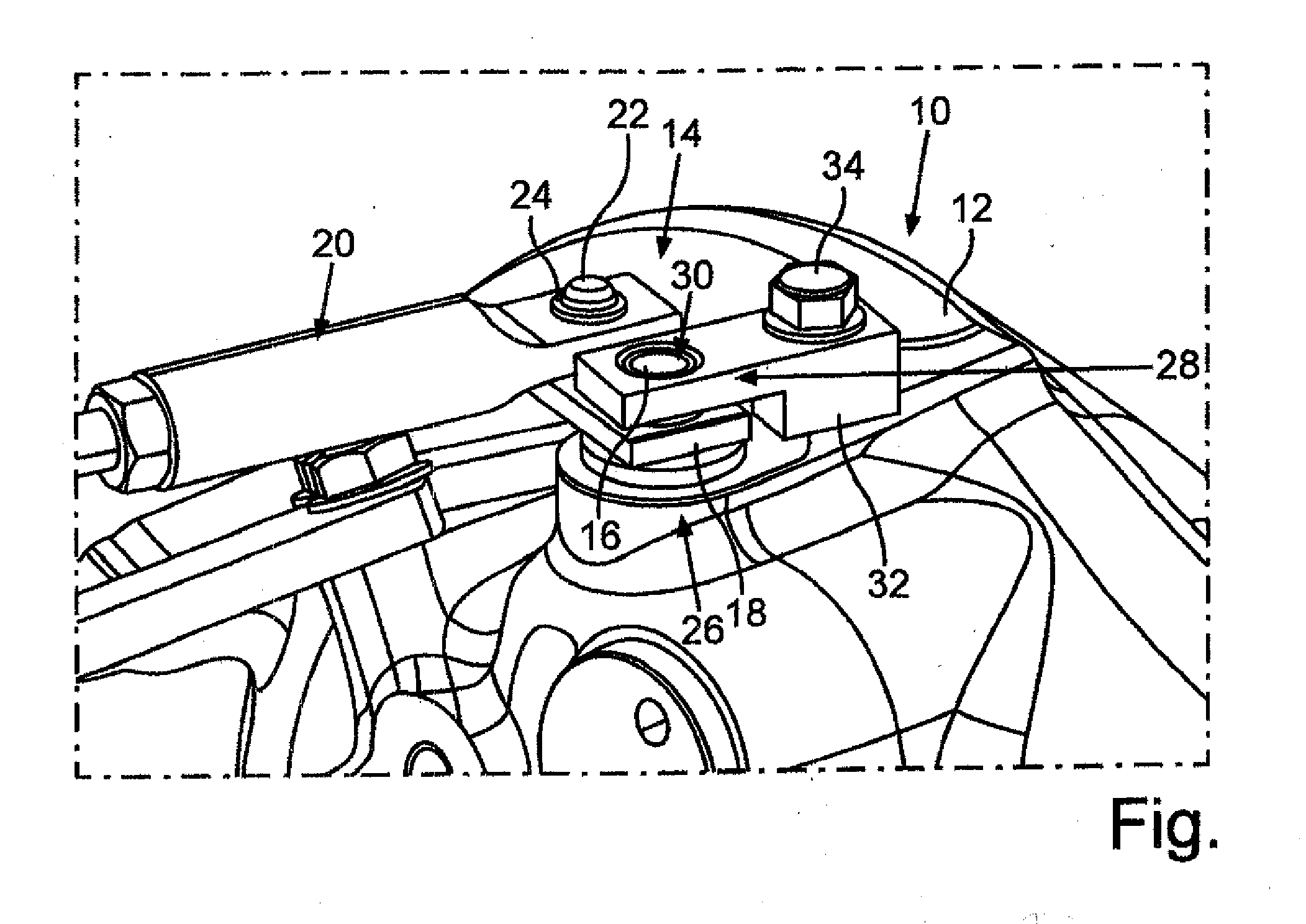
[0017]In a sectional and schematic perspective view, the FIGURE shows a turbine of an exhaust gas turbocharger designated as a whole by the numeral 10. The exhaust gas turbocharger is associated with an internal combustion engine of a motor vehicle, which is not shown in the FIGURE, and serves to supply the internal combustion engine with compressed air. For this purpose, the exhaust gas turbocharger includes a compressor with a compressor wheel which is connected to a rotor shaft of the exhaust gas turbocharger for rotation therewith. By the exhaust gas turbocharger, fresh air can be compressed to a charge-air pressure at which the air is fed to the internal combustion engine.

[0018]The turbine 10 includes a turbine housing 12 with a receiving space, which cannot be seen in the FIGURE and in which a turbine wheel of the turbine 10 is accommodated. The turbine housing 12 is a housing element of the exhaust gas turbocharger. The turbine wheel is firmly connected to the rotor shaft. Th...


PUM


Abstract

In a valve device for a turbine of an exhaust gas turbocharger having a valve element for adjusting the pressure of the charge air supplied to, and pressurized by, the exhaust gas turbocharger, wherein the valve element is mounted on a shaft which is rotatably supported at a first bearing point on a housing element so that the valve element can be pivoted about an axis of rotation relative to the housing element by an actuating element connected to the shaft adjacent the housing element, the shaft is further supported at a second bearing point which is spaced from the first bearing point and disposed at the side of the actuating element remote from the housing element.

Description

[0001]This is a Continuation-in-Part application of pending international patent application PCT / EP2013 / 002947 filed Oct. 1, 2013 and claiming the priority of German patent application 10 2012 024 300.6 filed Dec. 12, 2012.BACKGROUND OF THE INVENTION [0002]The invention relates to a valve device for a turbine of an exhaust gas turbocharger which has a valve element for adjusting the charge air pressure that is coupled to a shaft to be actuated thereby.[0003]Modern internal combustion engines are ever more frequently fitted with an exhaust gas turbocharger in order to be able to realize efficient and therefore low-fuel-consumption operation and, at the same time, very high specific power and torque generation of the internal combustion engine. The internal combustion engine can be a diesel engine or a spark ignition engine or some other kind of internal combustion engine.[0004]Such an exhaust gas turbocharger usually comprises a turbine with a turbine wheel and a compressor with a co...

Claims


Application Information

Patent Timeline
Patent Type & Authority Applications(United States)
IPC IPC(8): F02B37/18
CPCF02B37/186F16K1/224Y02T10/12
Inventor MUELLER, MARKUSGUTMANN, CORNELSEEGER, ANNETTE
Owner DAIMLER AG
Why Eureka
Try Eureka