
Method for operating a once-through steam generator and forced-flow steam generator

a once-through steam generator and steam generator technology, applied in the direction of water feed control, lighting and heating apparatus, boiler control, etc., can solve the problems of inability to draw any acceptable conclusion, inability to meet the needs of the customer, so as to achieve reliable prediction adaptation, reliable, stable regulation behavior

Active Publication Date: 2016-11-01
SIEMENS ENERGY GLOBAL GMBH & CO KG
View PDF89 Cites 1 Cited by
  • Summary
  • Abstract
  • Description
  • Claims
  • Application Information

AI Technical Summary

Benefits of technology

The invention is about a method for operating a once-through steam generator that allows for efficient and reliable regulation of the supply water flow through the evaporator heating surface. The method takes into account the current temperature and mass flow of the flow medium on entry into the hot gas duct and uses this information to predict the expected demand for the heat output. This allows for a predictive or preventive determination of the supply water mass flow target value, which ensures a stable and reliable regulation of the supply water flow and low deviation from the target value, regardless of the operating state of the steam generator. Overall, this method results in a simplified and reliable method for regulating the steam output of a once-through steam generator.

Problems solved by technology

In this case it should particularly be taken in account that, unlike with fired boilers, in this case the firing power is not a suitable parameter which allows a sufficiently reliable deduction of the underlying heat flow balance.
In particular account should be taken in this case that for an equivalent value for waste-heat boilers, namely the current gas turbine power or parameters correlating with this, further gas-turbine-internal parameters can also occur, so that on the basis of these values it is not possible to draw any acceptable conclusion about the enthalpy circumstances on entry of the hot gas into the flue gas duct of the steam generator.

Method used


Image

  • Method for operating a once-through steam generator and forced-flow steam generator
  • Method for operating a once-through steam generator and forced-flow steam generator
  • Method for operating a once-through steam generator and forced-flow steam generator

Examples


Embodiment Construction

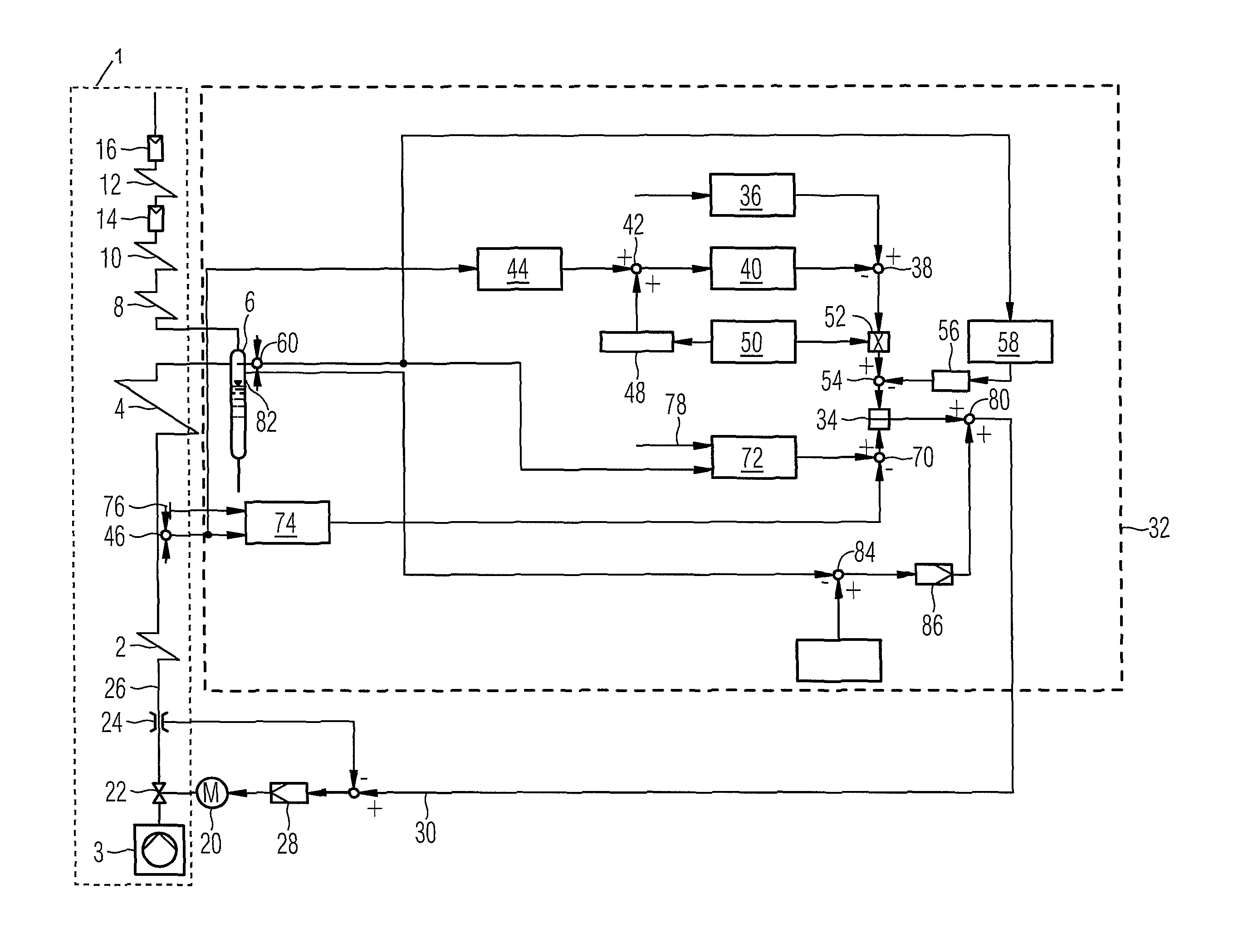
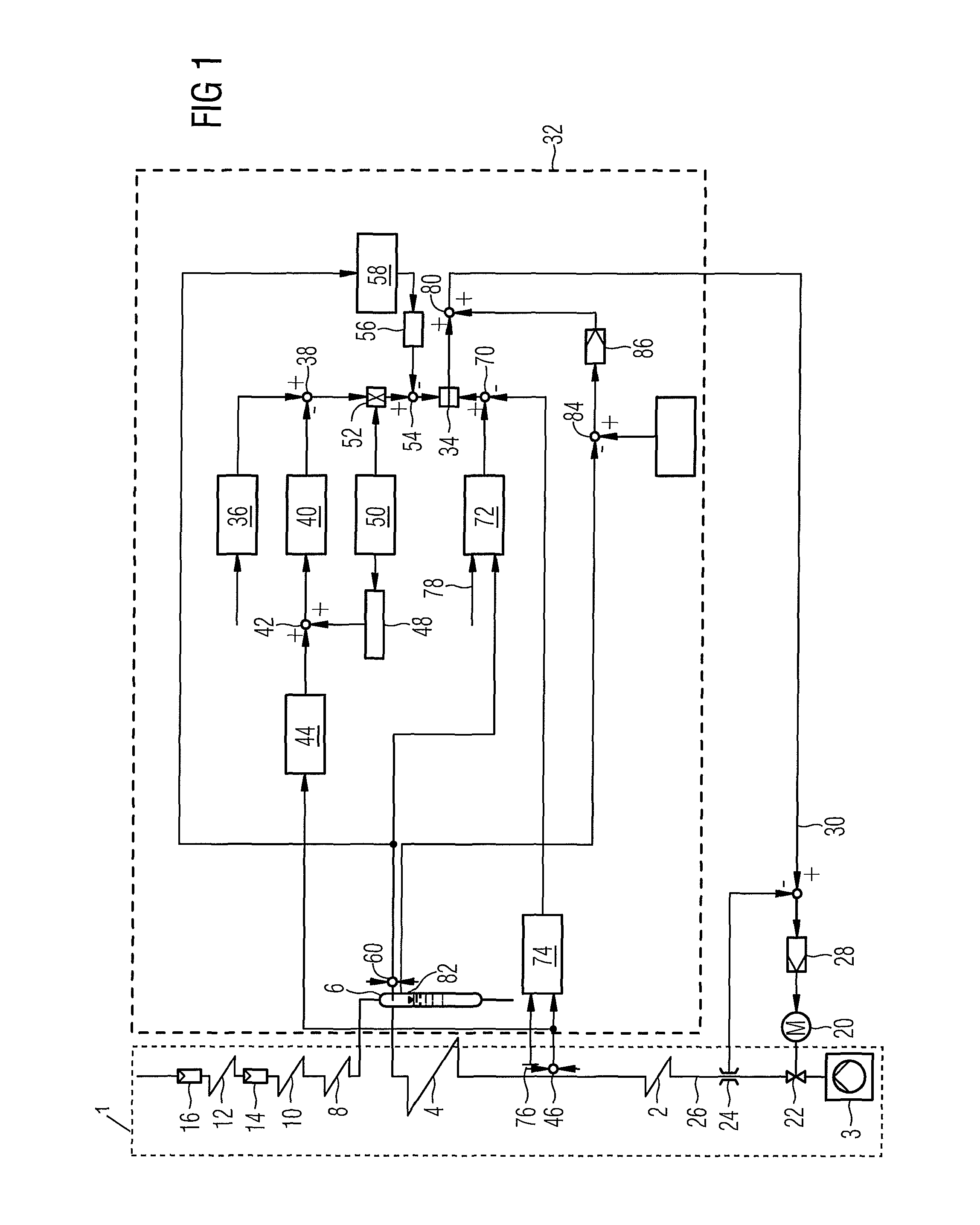
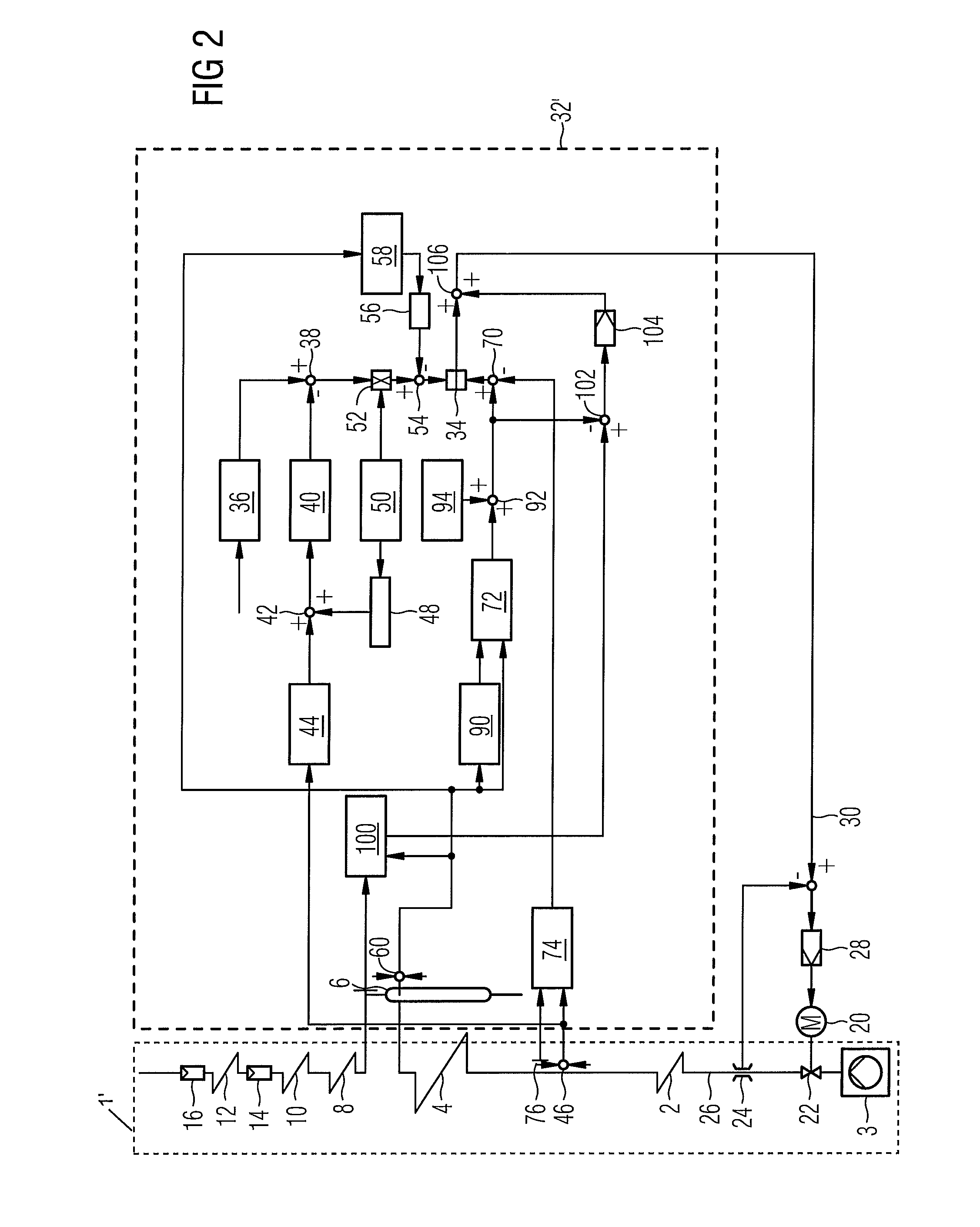
[0025]The forced-flow steam generators 1, 1′ in accordance with FIG. 1, 2 each feature a preheater referred to as an economizer 2 for supply water intended as a flow medium which is located in a gas pipe not shown a greater detail. The economizer 2 is connected on the flow medium side upstream from a supply water pump 3 and downstream from an evaporator heating surface 4. On the output side the evaporator heating surface 4 is connected via a water reservoir 6 which can also especially be embodied as a water separator or separation vessel, to a number of downstream superheater heating surfaces 8, 10, 12, which for their part can be provided, for adapting the steam temperatures and the like, with injection coolers 14, 16. The forced-flow steam generators 1, 1′ are each embodied as a waste-heat boiler or waste-heat steam generator, with the heating surfaces, i.e. especially of the economizer 2, the evaporator heating surface 4 as well as the superheater heating surfaces 8, 10, 12 being...


PUM


Abstract

A method for operating a once-through steam generator including an evaporator heating surface is provided. A target value for the supply water mass flow is fed to a device for setting the supply water mass flow, which is predefined using the ratio of the heat flow currently being transferred in the evaporator heating surface from the hot gas to the flow medium to a target enthalpy increase predefined with respect to the desired live steam condition of the flow medium in the evaporator heating surface. A forced-flow steam generator used for carrying out the method is also provided. The heat flow transferred from the hot gas to the flow medium is ascertained for this purpose allowing for a specific temperature value characteristic of the current temperature of the hot gas at the evaporator inlet and a specific mass flow value characteristic for the current mass flow of the hot gas.

Description

CROSS REFERENCE TO RELATED APPLICATIONS[0001]This application is the US National Stage of International Application No. PCT / EP2008 / 065522, filed Nov. 14, 2008 and claims the benefit thereof. The International Application claims the benefits of European Patent Office application No. 07023081.8 EP filed Nov. 28, 2007. All of the applications are incorporated by reference herein in their entirety.FIELD OF INVENTION[0002]The invention relates to a method for operating a once-through steam generator having an evaporator heating surface in which a device for setting the supply water mass flow {dot over (M)} is fed a target value {dot over (M)}s for the supply water mass flow {dot over (M)}. It further relates to a forced-flow steam generator for carrying out the method.BACKGROUND OF INVENTION[0003]In a once-through steam generator the heating of a number of steam generator tubes which together form an evaporator heating surface leads to a complete evaporation of a flow medium in the steam...

Claims


Application Information

Patent Timeline
Patent Type & Authority Patents(United States)
IPC IPC(8): F22D5/26F22B35/12F22B35/10F22B37/38
CPCF22B37/38
Inventor BRUCKNER, JANFRANKE, JOACHIMTHOMAS, FRANK
Owner SIEMENS ENERGY GLOBAL GMBH & CO KG
Learn More