Micromechanical sensor

a sensor and micro-mechanical technology, applied in the direction of turning-sensitive devices, acceleration measurement using interia forces, instruments, etc., can solve the problems of relatively high peak stress of bending spring devices, spring damage, and damage to springs, so as to reduce stress peaks, avoid high bending rates, and reduce stress peaks

Active Publication Date: 2014-09-09
HANKING ELECTRONICS LTD
View PDF12 Cites 0 Cited by
  • Summary
  • Abstract
  • Description
  • Claims
  • Application Information

AI Technical Summary

Benefits of technology

[0021]A particularly weak inner curvature is achieved when the inflection region of the meander conforms to the inner circle of curvature by greater than 180°. As a result of the large radius of curvature of the inner circle of curvature which is thus made possible, this advantageously causes peak stresses to be distributed over a larger area, thus allowing them to be kept low.
[0016]In one advantageous embodiment of the invention, another measure for reducing the load on the bending spring device may be achieved by the rounded transition having a non-constant radius of curvature. The meanders as well as the spring bars are thus connected to the adjacent components in a particularly gentle manner with regard to their stresses. The uniformity of the bending and the associated accuracy of the measurement by the sensor are thus improved.
[0021]A particularly weak inner curvature is achieved when the inflection region of the meander conforms to the inner circle of curvature by greater than 180°. As a result of the large radius of curvature of the inner circle of curvature which is thus made possible, this advantageously causes peak stresses to be distributed over a larger area, thus allowing them to be kept low.
[0023]To obtain a large contact of the circle(s) of curvature, it is advantageous when the circle of curvature of the outer midpoint, or, for multiple outer circles of curvature, the circles of curvature of the outer midpoints, conform(s) overall to the meander by greater than 90°. A concave or convex curvature of the meander is thus achieved.
[0016]In one advantageous embodiment of the invention, another measure for reducing the load on the bending spring device may be achieved by the rounded transition having a non-constant radius of curvature. The meanders as well as the spring bars are thus connected to the adjacent components in a particularly gentle manner with regard to their stresses. The uniformity of the bending and the associated accuracy of the measurement by the sensor are thus improved.

Problems solved by technology

However, shock effects due to impacts to the sensor may cause extreme bending stresses which may result in damage to the bending spring device.
One disadvantage of the prior art is that relatively high peak stresses occur in the bending spring devices during extreme deflections of the sensor mass.
This may result in damage to the springs, and thus, to the entire sensor.
In particular, the springs may break or become torn, thus hindering or completely preventing the movability of the sensor mass.
When the meander and / or the spring bar has / have a convex curvature, this results in a bending characteristic which reduces stress peaks even in extreme situations, such as mechanical shock events, for example.

Method used


Image

  • Micromechanical sensor
  • Micromechanical sensor
  • Micromechanical sensor

Examples


Embodiment Construction

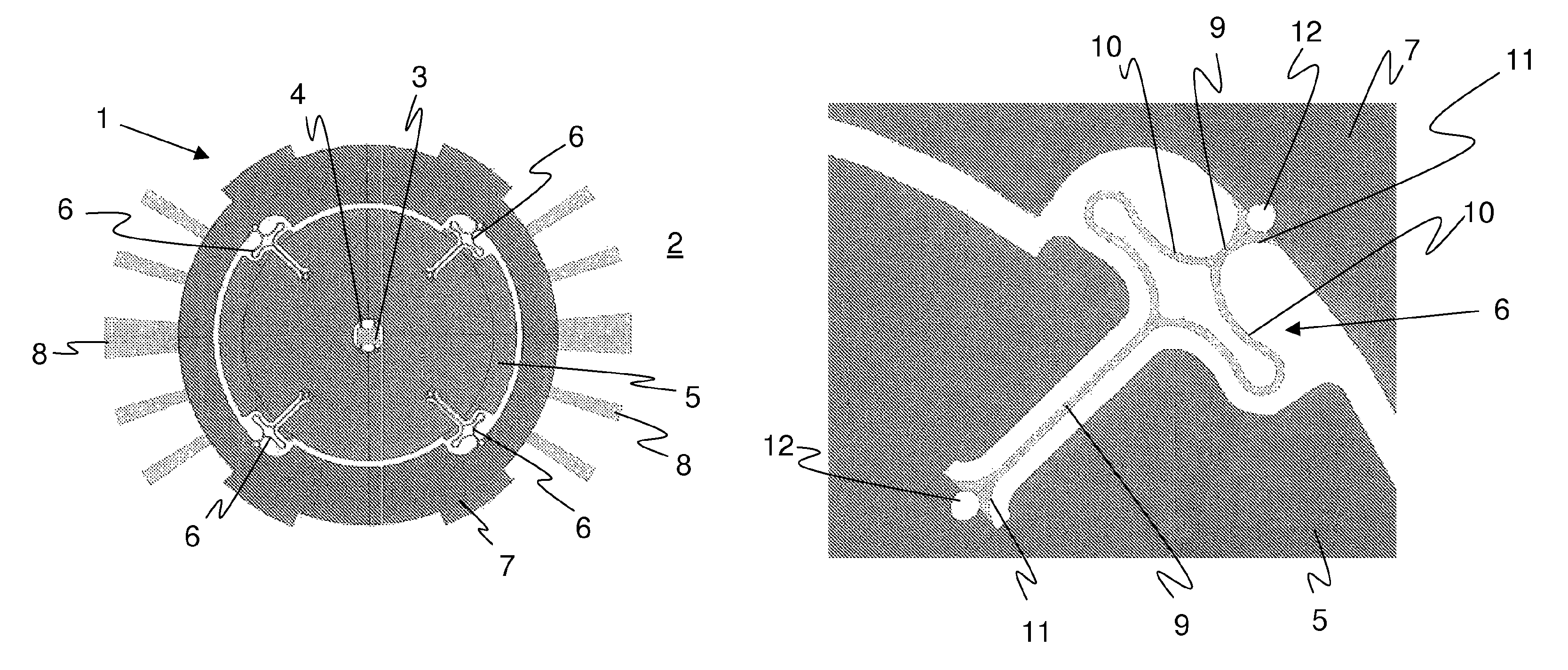
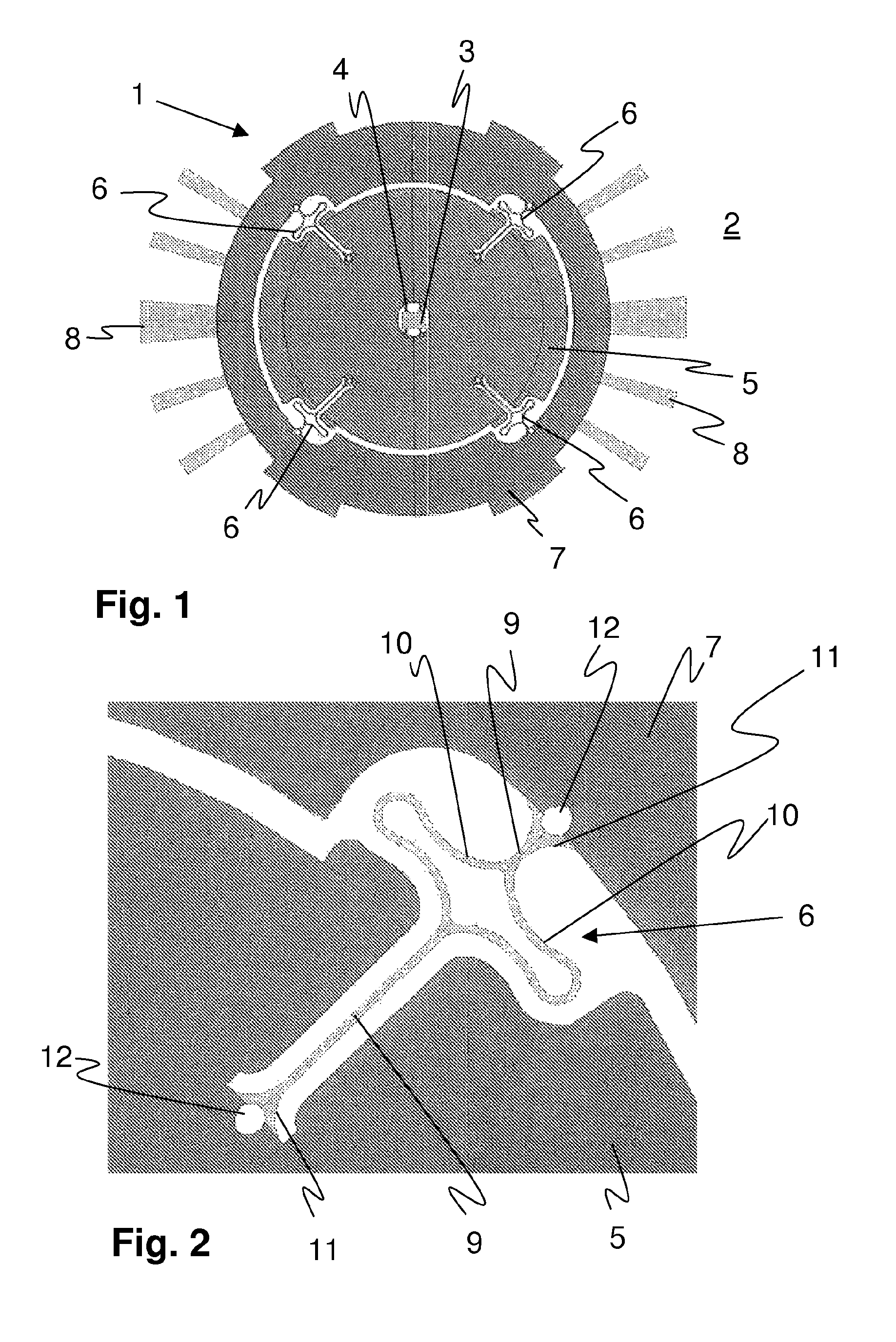
[0030]FIG. 1 shows a top view of a sensor 1 according to the invention, in the present case, a yaw rate sensor for detecting rotations of the sensor 1 about an axis. An anchoring 3 is situated on a substrate 2 of the sensor 1, and a sensor mass 5 is rotatably fastened to the anchoring by means of four springs 4. The sensor mass 5 is connected to the drive mass 7 by means of a bending spring device 6. Four of the bending spring devices 6 are uniformly distributed at the periphery of the sensor mass 5. The drive mass 7, by means of electrodes 8 attached thereto, is to be set in a primary motion in which it vibrates in an oscillating manner about the z axis which projects out of the plane of the drawing. This primary motion is completed almost exclusively by the drive mass 7, and does not continue on the sensor mass 5. Thus, the sensor mass 5 does not take part in the primary motion of the drive mass 7. If the substrate 2, i.e., the sensor 1, then rotates about an x or y axis situated ...


PUM


Abstract

A micromechanical sensor comprising a substrate (5) and at least one mass (6) which is situated on the substrate (5) and which moves relative to the substrate (5) is used to detect motions of the sensor due to an acceleration force and / or Coriolis force which occur(s). The mass (6) and the substrate (5) and / or two masses (5, 7) which move toward one another are connected by at least one bending spring device (6). The bending spring device (6) has a spring bar (9) and a meander (10), provided thereon, having a circle of curvature (K1; K6; K8; K9; K11) whose midpoint (MP1; MP6; MP8; MP9; MP11) and radius of curvature (r1; r6; r8; r9; r11) are inside the meander (10). For reducing stresses that occur, in addition to the radius of curvature (r1; r6; r8; r9; r11) having the inner midpoint (MP1; MP6; MP8; MP9; MP11), the meander (10) has at least one further radius of curvature (r2; r3; r4; r5; r7; r10) having a midpoint (MP2; MP3; MP4; MP5; MP7; MP10) outside the meander (10). The at least one further radius of curvature (r2; r3; r4; r5; r7; r10) is situated between the meander (10) and the spring bar (9).

Description

CROSS REFERENCE TO RELATED PATENT APPLICATIONS[0001]This application is the National Phase Application under 35 USC §371 of International Application No. PCT / EP2010 / 055634, filed Apr. 27, 2010, which claims priority to German Patent Application 10 2009 0002 702.5, filed Apr. 28, 2009.BACKGROUND[0002]A. Technical Field[0003]The present invention relates to a micromechanical sensor comprising a substrate and at least one mass which is situated on the substrate and which moves relative to the substrate for detecting motions of the sensor due to an acceleration force and / or Coriolis force which occur(s), the mass and the substrate and / or two masses which move toward one another being connected by at least one bending spring device, and the bending spring device having a spring bar and a meander, provided thereon, having a circle of curvature whose midpoint is inside the meander.[0004]B. Background of the Invention[0005]Micromechanical sensors are used for detecting accelerations and / or ...

Claims


Application Information

Patent Timeline
Patent Type & Authority Patents(United States)
IPC IPC(8): G01C19/56G01P15/02
CPCG01P15/0888G01C19/5712G01P15/08
Inventor HAMMER, HANNO
Owner HANKING ELECTRONICS LTD
Why Eureka
Try Eureka