Electrical connection structure, terminal structure, and vehicle

A structure and electrical connection technology, which is applied in the direction of conductive connection, motor generator connector, battery/battery traction, etc., to achieve the effect of saving space, improving freedom, and improving vibration resistance

Active Publication Date: 2017-08-15
HONDA MOTOR CO LTD
View PDF6 Cites 2 Cited by
  • Summary
  • Abstract
  • Description
  • Claims
  • Application Information

AI Technical Summary

Problems solved by technology

For example, in an environment prone to vibration like a vehicle, there is room for improvement from the viewpoint of stable contact for a single contact point

Method used


Image

  • Electrical connection structure, terminal structure, and vehicle
  • Electrical connection structure, terminal structure, and vehicle
  • Electrical connection structure, terminal structure, and vehicle

Examples


no. 1 approach

[0065]

[0066] [A-1-1. Overall structure]

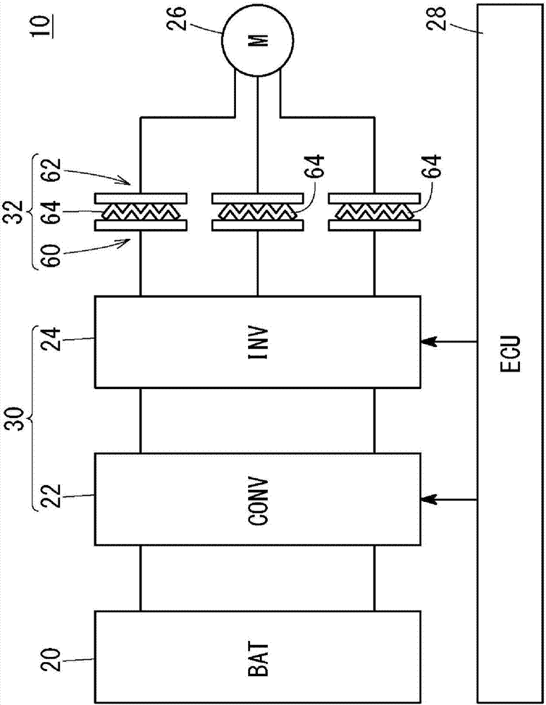
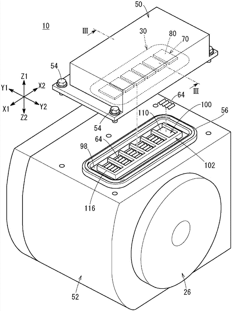
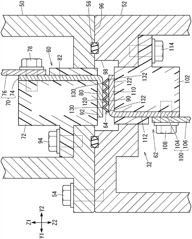
[0067] figure 1 It is a diagram showing a part of electric circuits of the vehicle 10 according to the first embodiment of the present invention. figure 2 It is a perspective view schematically showing a part of the vehicle 10 according to the first embodiment. image 3 is briefly shown figure 2 Sectional view of the III-III line section. figure 2 as well as image 3 Arrows X1 and X2 in the figure represent the front-rear direction of the vehicle 10, arrows Y1 and Y2 represent the width direction of the vehicle 10, and arrows Z1 and Z2 represent the up-down direction of the vehicle 10 (described later). Figure 5 as well as Figure 6 is also the same). The vehicle 10 of the first embodiment is a so-called battery vehicle. Alternatively, vehicle 10 may be an electric vehicle such as a hybrid vehicle.

[0068] Such as figure 1 As shown, the vehicle 10 has a battery 20 , an inverter 22 , an inverter 24 , a travel motor 26...

no. 2 approach

[0126]

[0127] [B-1-1. Overall structure (differences from the first embodiment)]

[0128] Figure 4 It is a diagram showing a part of electric circuits of the vehicle 10A according to the second embodiment of the present invention. Figure 5 It is a perspective view schematically showing a part of the vehicle 10A according to the second embodiment. Figure 6 is briefly shown Figure 5 Sectional view of the section along line VI-VI. The same reference numerals are attached to the same components as those in the first embodiment, and detailed description thereof will be omitted.

[0129] The electrical connection structure 32 of the first embodiment is provided at the portion where the motor 26 and the PCU 30 are connected ( figure 1 ), the first terminal structure 60 is set on the PCU case 50, and the second terminal structure 62 is set on the motor housing 52 ( figure 2 as well as image 3 ). On the other hand, the electrical connection structure 32a of the second ...


PUM


Abstract

An electrical connection structure includes a first conductor, a second conductor, and a conductive spring. The first conductor includes a first plate. The second conductor includes a second plate opposite to the first plate. The conductive spring is provided between the first plate and the second plate so as to be pressed by the first plate and the second plate. The conductive spring includes a plurality of first contact points contacting with the first plate and a plurality of second contact points contacting with the second plate.

Description

technical field [0001] The present invention relates to a manufacturing method of an electrical connection structure, a terminal structure, a vehicle, and an electrical connection structure capable of improving the degree of freedom of design, saving space, or stabilizing an electrical contact state. Background technique [0002] A structure for realizing electrical connection in a vehicle has been proposed (Patent Document 1, Patent Document 2). [0003] Patent Document 1 discloses a structure including a connecting member provided on either one of the facing portion 25 of the motor 11 or the facing portion 28 of the inverter 24 and protruding toward the other. The bus bar 23 and the remaining contacted portion 26 provided on the opposite side and in contact with the bus bar 23 electrically connect the motor 11 and the inverter 24 (abstract of specification). In one embodiment, the contacted portion 26 is a downwardly opening socket that accepts the bus bar 23 extending up...

Claims


Application Information

Patent Timeline
Patent Type & Authority Applications(China)
IPC IPC(8): H01R9/28H01R25/16B60K1/00
CPCB60K1/00H01R9/28H01R25/16B60L50/51H01R11/11H01R13/2421H01R13/5219H01R2107/00H01R2201/10H02K5/225H02K11/33Y02T10/70B60L3/12H01R13/2428H02P27/06
Inventor 后藤优介山口浩央大塚浩鹈饲伸周
Owner HONDA MOTOR CO LTD
Why Eureka
Try Eureka