
Device for detecting camera module along horizontal direction, and camera module detecting method

A camera module and horizontal technology, applied in image communication, television, electrical components, etc., can solve the problems of low detection efficiency, poor detection effect of detection equipment, and affecting the detection effect and efficiency of camera modules

Active Publication Date: 2015-11-11
NINGBO SUNNY OPOTECH CO LTD
View PDF5 Cites 15 Cited by
  • Summary
  • Abstract
  • Description
  • Claims
  • Application Information

AI Technical Summary

Problems solved by technology

The equipment used to detect the camera module in the prior art is carried out manually, and the camera module is sequentially detected along the longitudinal direction for each focus position (including near focus, middle focus and far focus) and contamination of the camera module. In some cases, there are many problems in this detection method, which affect the detection effect and efficiency of the camera module.
[0005] Specifically, firstly, the inspection equipment in the prior art has only one inspection station, and requires the manual operation of the inspector, that is to say, the inspector can only test a single camera module at a time when inspecting the camera module. The method leads to low detection efficiency. For example, in the actual application process, the detection efficiency UPH (UnitsPerHour, generated per hour) of the detection method of the camera module in the prior art is only 70pcs (Pieces, pieces)
In addition, when testing the camera module with the testing equipment of the prior art, the test seat used to fix the camera module needs to be manually rotated. Therefore, during the rotation, due to the accuracy of the equipment and the labor Due to reasons such as accuracy, the verticality of the test seat after being rotated cannot be guaranteed, so that the consistency of the test results for different camera modules is relatively poor
[0006] Furthermore, when the detection equipment in the prior art detects the near focus, middle focus and far focus of the camera module, the positions of the near focus light source and the far focus light source are fixed by magnets, so that when different camera modules are tested, each The positions of near focus, middle focus and far focus of a camera module cannot be guaranteed to be consistent
Especially when testing the telephoto of the camera module, the position of the teleconverter used to assist the testing process cannot be adjusted, and it is impossible to ensure that the central axis of the teleconverter is aligned with the central axis of the camera module
In addition, the inspection method of the inspection equipment in the prior art for the camera module is carried out along the longitudinal direction, so a working channel needs to be reserved on the upper part of the inspection equipment, so that the light from the external environment can easily enter the interior of the inspection equipment through this working channel , and cause interference to the detection light source, so the semi-closed design scheme leads to poor detection effect of the detection equipment in the prior art
And the function of the detection equipment of prior art is relatively simple, can't general AF (AutoFocus, automatic focusing) burning and AF detection

Method used


Image

  • Device for detecting camera module along horizontal direction, and camera module detecting method
  • Device for detecting camera module along horizontal direction, and camera module detecting method
  • Device for detecting camera module along horizontal direction, and camera module detecting method

Examples


Embodiment Construction

[0077] The present invention will be further described below with reference to the accompanying drawings and embodiments, so that anyone skilled in the art can make and use the present invention. The embodiments in the following description are by way of example only and modifications will be apparent to those skilled in the art. The general principles defined in the following description will apply to other embodiments, alternatives, modifications, equivalent implementations and applications without departing from the spirit and scope of the invention.

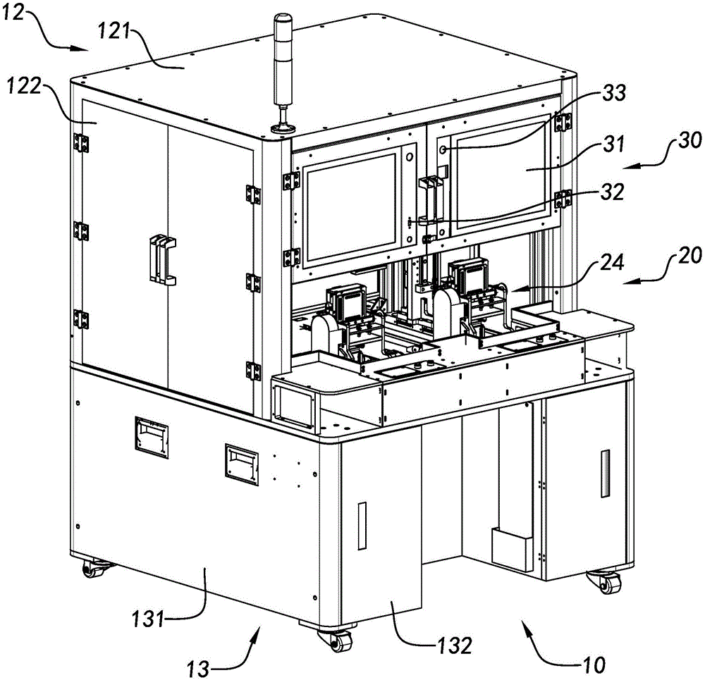
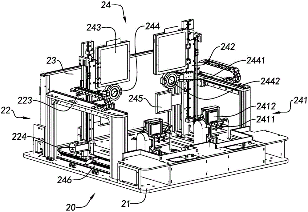
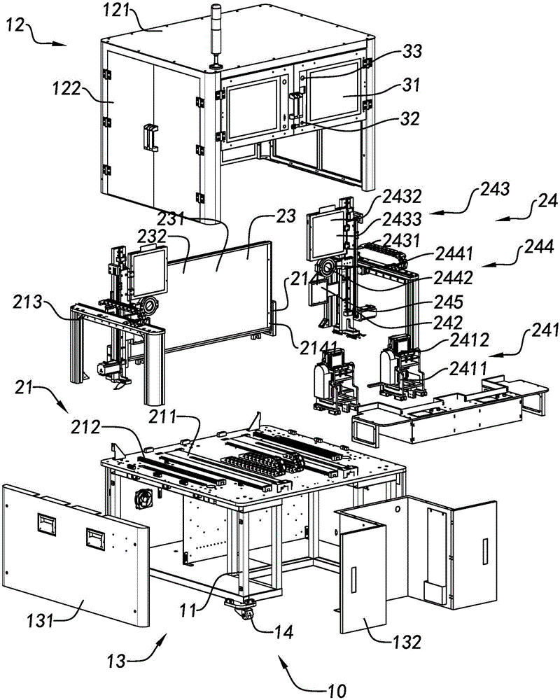
[0078] like Figure 1 to Figure 3 As shown, the detection device according to a preferred embodiment of the present invention will be disclosed and explained, wherein the detection device is especially suitable for detecting or burning various parameters of a high-pixel camera module that applies optical image stabilization technology . The detection device includes a support unit 10 and a detection unit 20, the detection u...


PUM


Abstract

The invention discloses a device for detecting a camera module along a horizontal direction, and a camera module detecting method. The detecting device is provided with a near-focus light source, a teleconverter, a dirt defective pixel light source and a far-focus light source which are arranged along the horizontal direction and have a vertical extending direction. When the camera module is detected, the camera module moves along the horizontal direction, so that the posture of the camera module is more consistent with the use posture of the camera module while a user uses a mobile electronic equipment having the camera module to shoot an image. Compared with the mode of detecting the camera module along a vertical direction in the prior art, the detecting result of detecting the camera module with the detecting device better matches an actual condition.

Description

technical field [0001] The invention relates to a detection device of a camera module and a detection method thereof, in particular to a device for detecting a camera module along a horizontal direction and a detection method thereof. Background technique [0002] As users have higher and higher requirements for the image quality of mobile electronic devices, the camera modules installed in mobile electronic devices are used as hardware to assist users in shooting, and their quality is also more and more demanding. Therefore, , Improving the imaging effect of the camera module is urgent. [0003] At present, the OIS (Optical Image Stabilizer, Optical Image Stabilizer) camera module applying optical image stabilization technology, especially the high-pixel OIS camera module applying optical image stabilization technology provides a compensation mechanism based on hardware. The technology realizes the compensation for the shaking direction of the lens of the camera module and...

Claims


Application Information

Patent Timeline
Patent Type & Authority Applications(China)
IPC IPC(8): H04N17/00
Inventor 陈永明严春琦梁敬姣禹焕奇
Owner NINGBO SUNNY OPOTECH CO LTD
Learn More