
Tracheostomy tube with auxiliary sound valve function, flushable, suctionable and anti-aspiration

A sputum suction tube and intubation technology, which is applied in the direction of tracheal intubation, enema/irrigator, suction equipment, etc., can solve problems such as difficulty in speaking, and achieve the effect of stable intubation and humanized design experience

Active Publication Date: 2017-08-11
淄博恒智威通医疗器械科技有限公司
View PDF1 Cites 0 Cited by
  • Summary
  • Abstract
  • Description
  • Claims
  • Application Information

AI Technical Summary

Problems solved by technology

However, it is difficult for patients with tracheostomy to speak without pulling out the intubation body

Method used


Image

  • Tracheostomy tube with auxiliary sound valve function, flushable, suctionable and anti-aspiration
  • Tracheostomy tube with auxiliary sound valve function, flushable, suctionable and anti-aspiration
  • Tracheostomy tube with auxiliary sound valve function, flushable, suctionable and anti-aspiration

Examples


Embodiment 1

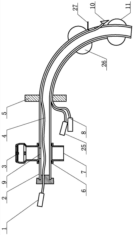
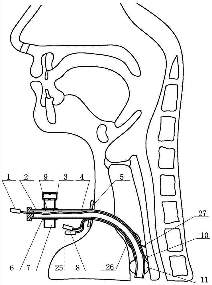
[0045] Such as figure 1 with 2 As shown, in the present invention, the cannula body 2 includes an insertion end and an external insertion end. On the tube wall of the intubation end of the intubation body 2, the first air bag 26 and the second air bag 11 are sequentially arranged from the outside to the inside, and the first air bag 26 and the second air bag 11 are respectively connected to the first inflation tube 25 and the second inflation tube 8; The tube wall of the intubation body 2 between the first air bag 26 and the second air bag 11 is provided with a valve 27 that is opened one-way outside the tube; it also includes a sputum suction tube 4, which is located in the intubation tube body 2 and sucks the sputum. One end of the sputum tube 4 passes through the insertion end of the intubation tube body 2 and connects to the sputum suction port 10 , and the other end of the sputum suction tube 4 passes through the external end of the intubation tube body 2 to connect to t...

Embodiment 2

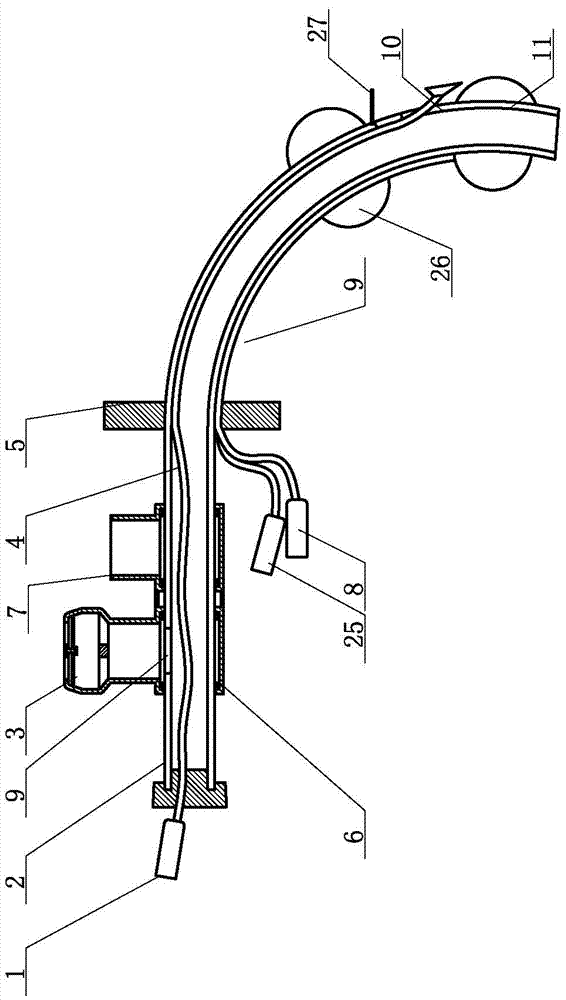
[0053] Such as image 3 with 4 As shown, the converter 6 is sleeved on the external end of the intubation body 2 in a tubular shape; the sounding valve and the oxygen supply interface 7 are in the shape of a "one" and are installed on the converter 6 through a sealing ring; along the intubation body 2 Move the converter 6 left and right, and the sounding valve and the oxygen and drug supply interface 7 can be connected to the air port 9 in turn. Other structures and usage methods are the same as those in Embodiment 1, and will not be repeated here.

Embodiment 3

[0055] The airflow heating device is set on the outer end of the intubation tube body.

[0056] Such as Figure 12-14 As shown, the airflow heating device includes an air inlet ring 32 and an inflatable ring 34, and four air columns 31 are arranged between the air inlet ring 32 and the inflatable ring 34; one end of the air column 31 communicates with the air inlet ring 32, and the other end of the air column 31 The gas nozzle 30 is connected to the inflation ring 34 . The gas inlet 28 is arranged on the gas inlet ring 32 , and the gas inlet 28 is connected to the gas source 33 . A pressure-sensitive release valve 29 is set on the inflation ring 34, and when the air pressure in the inflation ring 34 reaches a preset upper limit, the pressure-sensitive release valve 29 opens to release the gas pressure; when the air pressure in the inflation ring 34 reaches a preset When the lower limit is reached, the pressure-sensitive air release valve 29 is closed, and the process of air c...


PUM


Abstract

The utility model relates to a tracheotomy intubation tube which can be flushed, can suck sputum and prevent aspiration, and belongs to the field of medical devices. It is characterized in that it includes a cannula body, and the cannula body includes an insertion end and an external end; a first air bag and a second air bag are sequentially arranged on the wall of the inner end from outside to inside; between the first air bag and the second air bag The tube wall of the intubation body is provided with a valve that opens one-way to the outside of the tube; it also includes a sputum suction tube, which is located in the intubation body, and one end of the suction tube passes through the insertion end of the intubation body and connects to the suction port , the other end of the suction tube passes through the external end of the intubation body to connect to the suction connection port; the external end of the intubation body is provided with a sounding valve and an oxygen supply interface. The invention can make the patients undergoing tracheotomy use the tracheotomy intubation to assist breathing, and at the same time, can also achieve timely suction of sputum, prevent aspiration, provide more convenient oxygen supply, drug supply and vocalization.

Description

technical field [0001] The invention belongs to the field of medical equipment, and in particular relates to a tracheotomy intubation tube with the function of an auxiliary sounding valve, capable of flushing, sucking sputum, and preventing aspiration. Background technique [0002] Tracheotomy is to incise the cervical trachea and put in a tracheotomy tube. Tracheotomy is a common operation to relieve dyspnea caused by laryngeal origin, respiratory dysfunction or retention of secretions in the lower respiratory tract. . [0003] In the domestic medical field, in order to enable the conscious patient who has had a tracheotomy to speak, the simple method is to temporarily block the entrance of the intubation body with a cork, cotton swab, or adhesive tape. Otherwise, if the tube is blocked for too long, it will lead to chronic hypoxia in the patient and affect the functions of important organs such as the brain, heart, and lungs. In addition, if the sputum is viscous and can...

Claims


Application Information

Patent Timeline
Patent Type & Authority Patents(China)
IPC IPC(8): A61M16/04A61M1/00A61M3/02
Inventor 王洪泉姚军
Owner 淄博恒智威通医疗器械科技有限公司
Learn More