
A locking mechanism for installation on a faucet table and a method for installing the locking mechanism

The technology of a locking mechanism and an installation method, which is applied in the bathroom field, can solve the problems of small space under the installation surface of the faucet, difficulty in installing the locking mechanism of the faucet, and inconvenient operation for the installer, so as to improve installation efficiency, wide application range, and compact structure. easy to achieve effect

Active Publication Date: 2017-12-26
JOMOO KITCHEN & BATHROOM
View PDF4 Cites 13 Cited by
  • Summary
  • Abstract
  • Description
  • Claims
  • Application Information

AI Technical Summary

Problems solved by technology

[0002] At present, the installation structure of existing faucets is generally operated under the faucet installation surface (the faucet installation surface is even used for the faucet’s countertops, such as bathtubs, washstands and other countertops); the specific installation method is fixed by nut locking , the installer needs to penetrate under the installation table, first pre-tighten the faucet with bolts, then straighten the faucet body with one hand, and tighten the bolts with the other hand through tools; there are many shortcomings in the above installation method: first, the installation of the faucet The space under the surface is small, which is not convenient for installers to operate; secondly, the visibility is low and short tools are required to complete the installation. The operation is very inconvenient and laborious, especially for the installation of the faucet on the bathtub. Not only that, the existing installation steps are various and messy, and are easy to loosen after assembly and connection, and there are many tools used, usually requiring multiple tools to be used together; therefore, the existing faucet locking mechanism is difficult to meet the needs of installation

Method used


Image

  • A locking mechanism for installation on a faucet table and a method for installing the locking mechanism
  • A locking mechanism for installation on a faucet table and a method for installing the locking mechanism
  • A locking mechanism for installation on a faucet table and a method for installing the locking mechanism

Examples


Embodiment approach

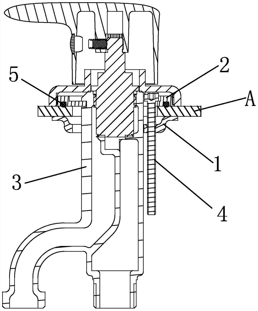
[0038] Specific implementation methods, such as Figure 1 to Figure 7 As shown, a locking mechanism for installation on a faucet platform according to the present invention mainly includes the following components: a faucet body 3, a locking block 1, a snap ring 2 and a connecting piece 4;

[0039] The present invention takes the installation of a bathtub faucet as an example, and the specific installation process is as follows:

[0040] Step 1: Insert the locking block 1 corresponding to the outer peripheral wall of the faucet body 3 and restrict the circumferential rotation of the locking block 1 with the faucet body 3 ; superior;

[0041]Step 2: Insert the clasp 2 into the faucet body 3 above the faucet installation table A, and rotate it at an angle in the circumferential direction to drive the faucet body 3 to hang on the clasp 2; then place the clasp 2 On the faucet installation surface A, the faucet body 3 is hung above the installation table A;

[0042] Step 3: Pass...

Embodiment

[0043] Example, the actual installation process is as follows:

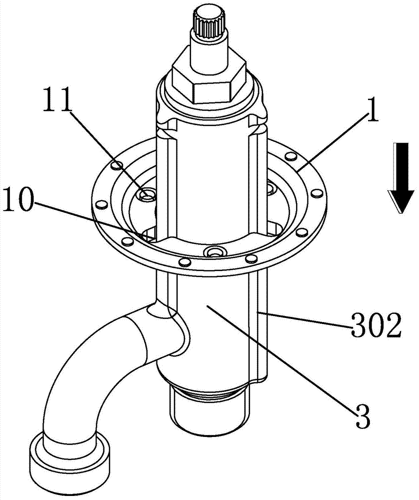
[0044] Step 1: (eg image 3 As shown), the locking block 1 is inserted into the limiting part 302 of the locking rib 30 on the outer peripheral wall of the faucet body 3, and is limited by the locking rib 30 and the second relief part 10 on the locking block 1. bit fit to limit the circumferential rotation of the locking block 1 on the outer periphery of the faucet body 3;

[0045] Step 2: (eg Figure 4 As shown) put the gasket 5 into the faucet body 3, and then install it integrally from bottom to top under the installation table of the bathtub faucet, and make one end of the faucet body 3 penetrate through the installation table of the bathtub faucet; through the setting of the gasket 5, it can effectively prevent Because the installation table A of the bathtub faucet is uneven, the bottom surface of the faucet body 3 is under uneven force, which reduces its service life;

[0046] Step 3: (eg Figure 5 As s...


PUM


Abstract

The invention discloses a locking mechanism and a method for installing the locking mechanism on a faucet platform. The locking mechanism includes a locking block, a snap ring, and a connecting piece passing through the snap ring and connecting with the locking block; The locking block is sleeved on the outer wall of the faucet body and located below the installation surface of the faucet; the clasp is inserted into the faucet body and attached above the faucet installation surface with a swivel structure; wherein, the snap ring is sleeved into the faucet body and circumferentially Rotate an angle to drive the faucet body to hang on the snap ring; the connecting piece runs through the snap ring and the faucet installation surface, and is adapted to the hole on the locking block, and the driving connecting piece drives the locking block to displace, so that The snap ring and the locking block clamp the installation surface of the faucet; the locking mechanism of the present invention has a simple structure and is easy to realize. improved installation efficiency.

Description

technical field [0001] The invention relates to the bathroom industry, in particular to a locking mechanism installed on a faucet and a method for installing the locking mechanism. Background technique [0002] At present, the installation structure of existing faucets is generally operated under the faucet installation surface (the faucet installation surface is even used for the faucet’s countertops, such as bathtubs, washstands and other countertops); the specific installation method is fixed by nut locking , the installer needs to penetrate under the installation table, first pre-tighten the faucet with bolts, then straighten the faucet body with one hand, and tighten the bolts with the other hand through tools; there are many shortcomings in the above installation method: first, the installation of the faucet The space under the surface is small, which is not convenient for installers to operate; secondly, the visibility is low and short tools are required to complete t...

Claims


Application Information

Patent Timeline
Patent Type & Authority Patents(China)
IPC IPC(8): E03C1/04
Inventor 林孝发林孝山金磊江前印廖生上
Owner JOMOO KITCHEN & BATHROOM
Learn More