Eureka AIR delivers breakthrough ideas for toughest innovation challenges, trusted by R&D personnel around the world.

Self-compensating automotive steering mechanism

A technology for steering mechanisms and automobiles, applied in mechanical equipment, rigid brackets of bearing components, bearing components, etc., can solve the problems of short service life of bushings, failure of bushings to automatically compensate for wear gaps, frequent replacement, etc., and prolong the service life. Effect

Active Publication Date: 2015-11-18
温州鸿鹏汽配制造有限公司
View PDF5 Cites 0 Cited by
  • Summary
  • Abstract
  • Description
  • Claims
  • Application Information

AI Technical Summary

Problems solved by technology

[0002] At present, the automobile steering mechanism mainly includes a rotating shaft and a shaft sleeve. A bushing is arranged between the axial rear end of the rotating shaft located in the shaft sleeve and the shaft sleeve. The axial front end of the rotating shaft located outside the shaft sleeve is connected with a drive Its oscillating drive mechanism is mainly driven by the driver turning the steering wheel and through some transmission devices. Since the rotating shaft swings for a long time under the drive of the above-mentioned driving mechanism, the wear between the rotating shaft and the bush will occur during use. Due to the wear and tear, the direction of the vehicle will vibrate and deviate during the driving process, and because the bushes in the steering mechanism of the existing automobile cannot automatically compensate for the wear gap after wear, the bushings have a short service life and are frequently replaced.

Method used


Image

  • Self-compensating automotive steering mechanism
  • Self-compensating automotive steering mechanism
  • Self-compensating automotive steering mechanism

Examples


Embodiment Construction

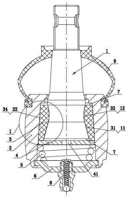
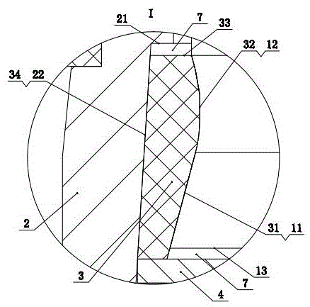
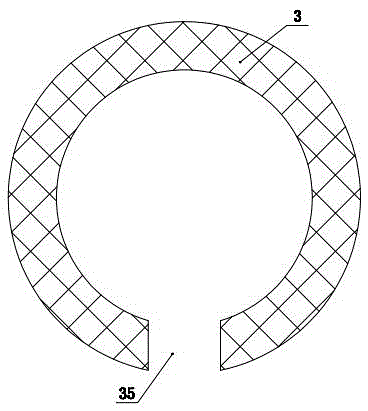
[0014] Such as figure 1 , 2 , 3 shows a self-complementary automobile steering mechanism, including a rotating shaft 1 and a shaft sleeve 2, and a bushing is arranged between the axial rear end of the rotating shaft 1 located in the shaft sleeve 2 and the shaft sleeve 2 3. The axial front end of the rotating shaft 1 located outside the sleeve 2 is connected with a driving mechanism to drive it to swing. The inner ring surface of the bushing 3 is composed of an inner tapered surface 31 with a narrow inside and a wide outside and a radial The arc-shaped surface 32 bowed inward is connected, and the inner tapered surface 31 is correspondingly located at the axial rear end, the arc-shaped surface 32 is correspondingly located at the axial front end, and the axial rear end of the rotating shaft 1 is Correspondingly, the tapered portion 11 fitted with the inner tapered surface 31 and the arc-shaped portion 12 fitted with the arc-shaped surface 32 are provided, and the axial rear en...


PUM


Abstract

The invention discloses a self-compensating automotive steering mechanism. The self-compensating automotive steering mechanism comprises a rotary shaft and a shaft sleeve. A bushing is arranged between the axial rear end, located in the shaft sleeve, of the rotary shaft and the shaft sleeve. A driving mechanism used for driving the rotary shaft to swing is connected to the axial front end, located outside the shaft sleeve, of the rotary shaft. The inner ring surface of the bushing is formed by connecting an inner conical surface with an arc-shaped surface, wherein the inner portion of the inner conical surface is narrow, the outer portion of the inner conical surface is wide, and the arc-shaped surface arches inwards in the radial direction. The inner conical surface is correspondingly located at the axial rear end. The arc-shaped surface is correspondingly located at the axial front end. A conical part matched with the inner conical surface in an attached mode and an arc-shaped part matched with the arc-shaped surface in an attached mode are correspondingly arranged at the axial rear end of the rotary shaft. A pushing mechanism which can push the bushing to slide forwards in the axial direction to achieve abrasion compensation is arranged at the axial rear end of the shaft sleeve. The pushing mechanism comprises a bushing liner plate, a spring and a rear cover. By the adoption of the structure, the service life of the automotive steering mechanism can be greatly prolonged.

Description

technical field [0001] The invention relates to an automobile steering mechanism. Background technique [0002] At present, the automobile steering mechanism mainly includes a rotating shaft and a shaft sleeve. A bushing is arranged between the axial rear end of the rotating shaft located in the shaft sleeve and the shaft sleeve. The axial front end of the rotating shaft located outside the shaft sleeve is connected with a drive Its oscillating drive mechanism is mainly driven by the driver turning the steering wheel and through some transmission devices. Since the rotating shaft swings for a long time under the drive of the above-mentioned driving mechanism, the wear between the rotating shaft and the bush will occur during use. Due to the wear and tear, the direction of the vehicle will vibrate and deviate during driving, and because the bushes in the steering mechanism of the existing automobile cannot automatically compensate for the wear gap after wear, the bushings hav...

Claims


Application Information

Patent Timeline
Patent Type & Authority Applications(China)
IPC IPC(8): F16C33/04F16C35/02F16C33/74
Inventor 林振长林群陈昆岳吕良斌
Owner 温州鸿鹏汽配制造有限公司
Why Eureka
Eureka Blog
Learn More