Supercharge Your Innovation With Domain-Expert AI Agents!

Ejector rod

A technology of ejector rods and connecting rods, applied in clutches, mechanical drive clutches, mechanical equipment, etc., can solve problems such as inconvenience, reduce the number of disassembly times, and avoid misalignment

Inactive Publication Date: 2015-11-18
JIANGYIN YUANWANG AUTO CLUTCH
View PDF0 Cites 0 Cited by
  • Summary
  • Abstract
  • Description
  • Claims
  • Application Information

AI Technical Summary

Problems solved by technology

[0002] The clutch ejector rod is used for the transmission of the clutch, but when there is a problem at either end of the ejector rod, both ends need to be disassembled for repair, which is very inconvenient

Method used


Image

  • Ejector rod

Examples


Embodiment Construction

[0008] All features disclosed in this specification, or steps in all methods or processes disclosed, may be combined in any manner, except for mutually exclusive features and / or steps.

[0009] Any feature disclosed in this specification (including any appended claims, abstract and drawings), unless expressly stated otherwise, may be replaced by alternative features which are equivalent or serve a similar purpose. That is, unless expressly stated otherwise, each feature is one example only of a series of equivalent or similar features.

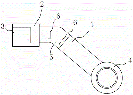
[0010] Such as figure 1 A push rod shown includes a connecting rod 1, a shaft sleeve 4 and a linkage head 2, one end of the connecting rod (1) is connected to the shaft sleeve 4, and a bump 6 is provided at the other end, and one end of the linkage head 2 is provided with Cylindrical through hole 3, the other end is a cylindrical structure, the end of the cylindrical structure is provided with a bump 6, the linkage head 2 and the connecting r...


PUM


Abstract

The invention discloses an ejector rod. When any end of the ejector rod goes wrong, the wrong end can be dismounted to be repaired without moving the other end of the ejector rod. The dismounting frequency of the ejector rod can be reduced as much as possible, and dislocation caused in the dismounting process of the ejector rod is avoided.

Description

technical field [0001] The invention relates to a push rod, in particular to a push rod for a clutch. Background technique [0002] The clutch ejector rod is used for the transmission of the clutch, but when any problem occurs at either end of the ejector rod, it is very inconvenient to disassemble both ends for repair. Contents of the invention [0003] The invention relates to a push rod, and only one end of the push rod can be removed during maintenance. [0004] In order to achieve this purpose, the structure adopted in the present invention is: a push rod, including a connecting rod, a shaft sleeve and a linkage head, one end of the connecting rod is connected to the shaft sleeve, and the other end is provided with a protrusion, and one end of the linkage head is There is a cylindrical through hole, the other end is a cylindrical structure, and the end of the cylindrical structure is provided with a bump. The linkage head and the connecting rod are connected to each ...

Claims


Application Information

Patent Timeline
IPC IPC(8): F16D23/12
Inventor 何春新
Owner JIANGYIN YUANWANG AUTO CLUTCH
Features
  • R&D
  • Intellectual Property
  • Life Sciences
  • Materials
  • Tech Scout
  • Unparalleled Data Quality
  • Higher Quality Content
  • 60% Fewer Hallucinations
Learn More