Compressor silencer assembling equipment and use method thereof

A technology for assembling equipment and silencers, which is applied in the field of compressor parts production, can solve the problems of reduced production accuracy, welding position deviation, and easy errors, etc., to reduce the number of disassembly and welding times, high welding position accuracy, and reduce The effect of assembly error

Active Publication Date: 2017-04-19
杭州瀚真电器制造有限公司
View PDF5 Cites 3 Cited by
  • Summary
  • Abstract
  • Description
  • Claims
  • Application Information

AI Technical Summary

Problems solved by technology

[0002] The surface of the casing of the compressor is a curved surface. To install the muffler on the casing requires repeated clamping of the casing and repeated manual welding. Since the surface of the casing is a curved surface, errors are likely to occur when the casing is repeatedly clamped, resulting in Deviations in welding positions reduce production accuracy
Moreover, repeated clamping and multiple welding waste time, reduce production efficiency, and cause large errors in manual positioning

Method used


Image

  • Compressor silencer assembling equipment and use method thereof
  • Compressor silencer assembling equipment and use method thereof
  • Compressor silencer assembling equipment and use method thereof

Examples


Embodiment 1

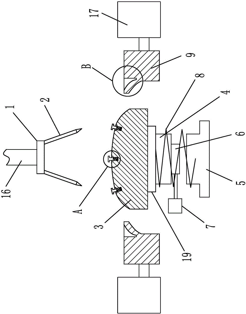
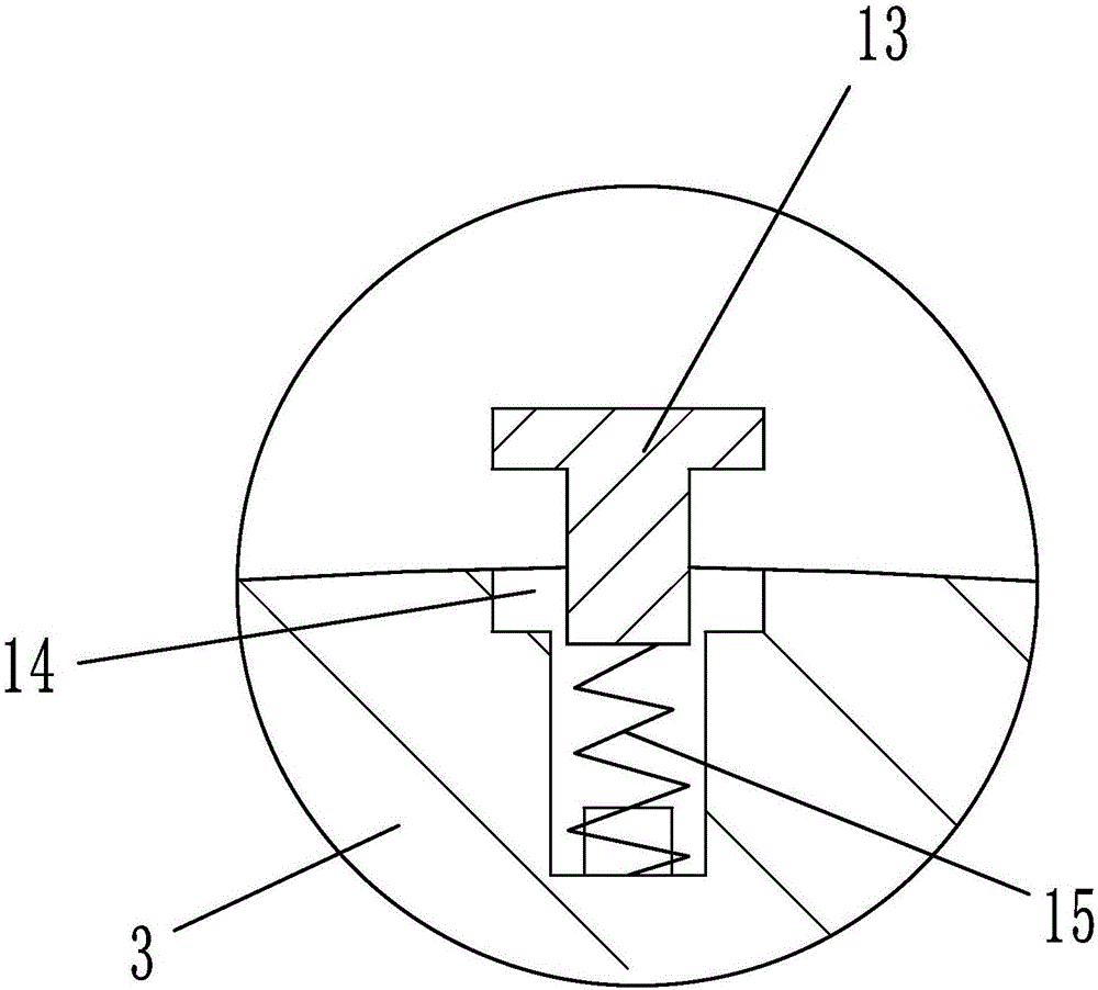
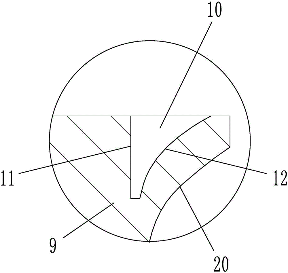
[0019] like figure 1 , 2 As shown in , 3 and 4, a compressor muffler assembly equipment includes a positioning head 3 that cooperates with the inner surface of the casing 18, claws 9 located on both sides of the positioning head and a welding mechanism located above the positioning head, and the positioning head is below the positioning head. A column 4 is arranged at the axis of the end face, and an electromagnetic suction sleeve 19 is set on the outer side of the column, and the upper end surface of the electromagnetic suction sleeve is bonded to the lower end surface of the positioning head. A positioning column 5 is arranged coaxially below the column, a positioning spring 8 is set on the outside of the column and the positioning column, a vibrating column 6 is arranged at the bottom of the column, and a vibrator 7 is connected to the vibrating column; The guide surface 20 that matches the shape of the outer surface of the positioning head, the edge of the upper end surfa...

Embodiment 2

[0022] Embodiment 2: The structure of this embodiment is basically the same as that of Embodiment 1, the difference is that, as Figure 6 , 7 As shown, the positioning head includes a left half head 31 and a right half head 32, and the middle part of the left half head and the right half head is provided with a positioning hole 26, and the positioning hole is provided with a positioning shaft 27 that cooperates with the positioning hole clearance. Position straight face 28 and sliding arc surface 29, the section of positioning hole is " D " font. The positioning head includes a left half head and a right half head. There are positioning holes in the middle of the left half head and the right half head. The positioning shaft is arranged in the positioning hole to fit with the positioning hole. The left half head and the right half head can be positioned through The shaft changes the distance between the two, which in turn changes the length of the positioning head, so that the...


PUM


Abstract

The invention relates to production of a compressor part, in particular to compressor silencer assembling equipment and a use method thereof. The compressor silencer assembling equipment comprises a positioning head matched with the inner surface of a machine enclosure, clamping claws located on two sides of the positioning head and a welding mechanism located above the positioning head, wherein a stand column is arranged on the axis of the lower end surface of the positioning head; the outer side of the stand column is sleeved with an electromagnetic attraction sleeve; the upper end surface of the electromagnetic attraction sleeve is attached to the lower end surface of the positioning head; a guide surface matched with the outer surface of the positioning head in shape is arranged on the end surface of the end, close to the positioning head, of each clamping claw; the welding mechanism comprises a positioning seat and a welding gun located on the positioning seat; the positioning seat is provided with an adjustment air cylinder used for controlling the positioning seat to ascend and descend; and adjustment heads are uniformly distributed on the outer surface of the positioning head. The compressor silencer assembling equipment and the use method thereof have the beneficial effects of being capable of effectively reducing the clamping frequency, increasing positioning accuracy, reducing the welding frequency, realizing simultaneous welding at multiple points, improving productivity and the like.

Description

technical field [0001] The invention relates to the production of compressor parts, in particular to a compressor muffler assembly equipment and a method for using the same. Background technique [0002] The surface of the casing of the compressor is a curved surface. To install the muffler on the casing requires repeated clamping of the casing and repeated manual welding. Since the surface of the casing is a curved surface, errors are likely to occur when the casing is repeatedly clamped, resulting in Deviations occur in the welding position, which reduces the production accuracy. Moreover, repeated clamping and multiple welding waste time, reduce production efficiency, and cause large errors in manual positioning. Contents of the invention [0003] The present invention mainly aims at the above problems, and provides a compressor muffler assembly equipment and its use method which can effectively reduce the clamping times, increase the positioning accuracy, reduce the w...

Claims


Application Information

Patent Timeline
Patent Type & Authority Applications(China)
IPC IPC(8): B23K31/02B23K37/02B23K37/04
CPCB23K31/02B23K37/0252B23K37/0435
Inventor 李斌
Owner 杭州瀚真电器制造有限公司
Why Eureka
Try Eureka