
Diaphragm for winding double-layer coil

A dual-coil, die-cut technology, applied in the direction of coil manufacturing, can solve the problem of inability to meet high-power power supplies, and achieve the effects of easy popularization and application, reduced production costs, and high production efficiency

Active Publication Date: 2015-11-18
ZHUHAI ZHIXIN AUTOMATIC TECH CO LTD
View PDF7 Cites 0 Cited by
  • Summary
  • Abstract
  • Description
  • Claims
  • Application Information

AI Technical Summary

Problems solved by technology

However, the self-adhesive coils currently on the market are generally single-layer, and all of them adopt an inside-out winding structure. This single-layer, inside-out self-adhesive coil cannot meet the needs of the rapid development of existing electronic appliances. , such as unable to meet the high-power power supply

Method used

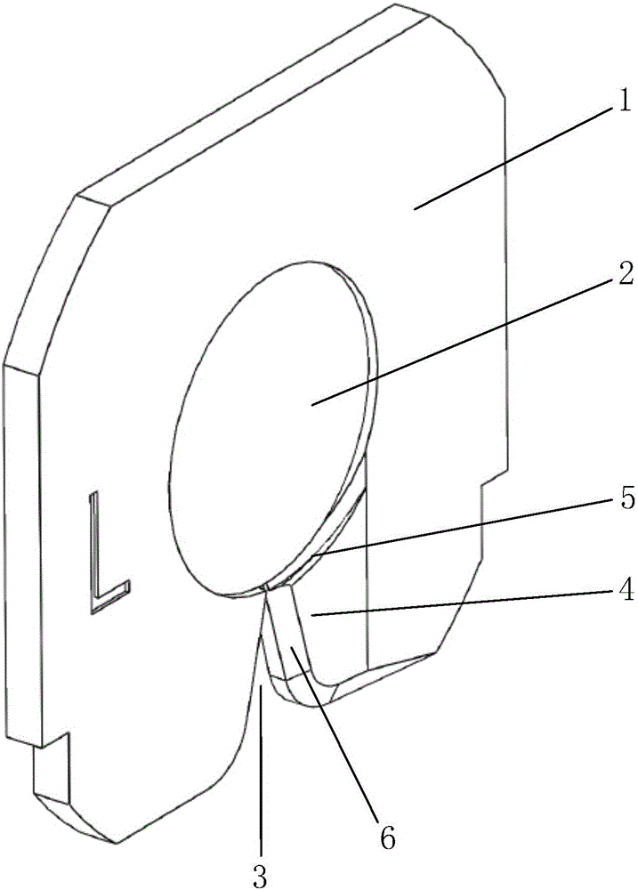

Image

  • Diaphragm for winding double-layer coil
  • Diaphragm for winding double-layer coil
  • Diaphragm for winding double-layer coil

Examples


Embodiment 1

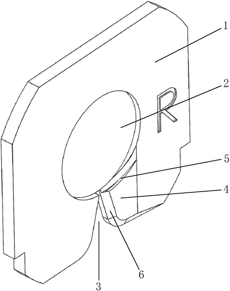
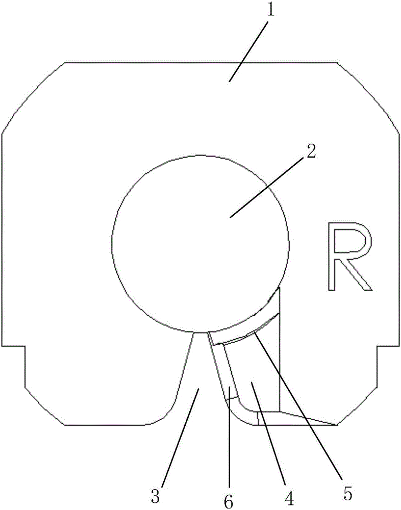
[0023] like Figure 1 to Figure 3 As shown in , the embodiment of the present invention provides a spacer for winding double coils, which includes a spacer body 1, and a winding shaft is provided in the middle of the left and right sides of the spacer body 1 The installation recess 2 is also provided with an entry line snap-in notch 3, the entry line snap-in notch 3 extends from the edge of the spacer body 1 to the bobbin installation recess 2, and gradually becomes smaller. Wherein, the thickness of the main body 1 of the spacer is 2 to 5mm, and the angle of the entry line snapping into the notch 3 is 30° to 60°; the installation recess 2 of the winding shaft and the entry line snapping into the notch 3 are both The septum main body 1 is integrally formed.

[0024] When using the spacer sheet for winding double coils described in the present invention, first place the spacer sheet between the left winding shaft and the right winding shaft of the self-adhesive coil winding ma...

Embodiment 2

[0028] like Figure 4 As shown in , the embodiment of the present invention provides a spacer for winding double coils, its structure is basically the same as that of Embodiment 1, including a spacer main body 1, and the left and right sides of the spacer main body 1 There is a winding shaft installation recess 2 in the middle of the sides of both sides, and the main body of the spacer 1 is provided with a notch 3 for entering the wire, and the notch 3 for the entry of the line extends from the edge of the main body 1 of the spacer to the winding The bobbin is installed in the concave position 2, and gradually becomes smaller. The only difference is that the main body 1 of the spacer is provided with two notches 3 for entering lines, and the two notches 3 for entering lines are symmetrically arranged on the upper and lower ends of the main body 1 of the spacer, wherein the spacers The mold body 1 is assembled by the left septum 11 and the right septum 12 and is left-right sym...


PUM

PropertyMeasurementUnit
Thicknessaaaaaaaaaa

Abstract

The invention relates to a diaphragm for winding a double-layer coil. The diaphragm comprises a diaphragm body, roll mounting concave positions are formed in the middles of the side surfaces on left and right sides of the diaphragm body, more than one wire inlet clamping gap is also formed on the diaphragm body, extends to the roll mounting concave positions from the edge of the diaphragm body, and becomes small gradually. With the diaphragm, the alpha-shaped double-layer self-adhesive coil with incoming and outdoing both from outside can be winded, so that the requirements of a large-power supply can be satisfied, the double-layer self-adhesive coils can be simultaneously winded, the production efficiency is extremely high, the production cost is low, and the space between the double layers of the self-adhesive coil can be accurately and stably controlled, the quality of a product is good, the technical difficulty which can not solved for a long time is solved, and in addition, the diaphragm is simple in structure, easy to process, low in cost, and easy for popularization and application.

Description

technical field [0001] The invention belongs to the technical field of self-adhesive coil winding, and in particular relates to a septum used for winding double coils. Background technique [0002] Self-adhesive coil is a coil made of self-adhesive wire wound by a winding machine. It is widely used in various equipment and electrical appliances, and its application range is very wide. However, the self-adhesive coils currently on the market are generally single-layer, and all of them adopt an inside-out winding structure. This single-layer, inside-out self-adhesive coil cannot meet the needs of the rapid development of existing electronic appliances. , such as unable to meet the high-power power supply. Contents of the invention [0003] In order to solve the above-mentioned technical problems existing in the prior art, the present invention provides an α-shaped double-layer self-adhesive coil that can be wound in and out, so as to meet the requirements of high-power powe...

Claims


Application Information

Patent Timeline
IPC IPC(8): H01F41/06
Inventor 张玮
Owner ZHUHAI ZHIXIN AUTOMATIC TECH CO LTD
Learn More