A chassis with electromagnetic shielding function

An electromagnetic shielding and functional technology, applied in circuits, electrical components, parts of connecting devices, etc., can solve the problems of limited location, inability to change the installation position of connectors, and inability to achieve effective shielding, preventing interference and satisfying installation requirements. The effect of position change

Active Publication Date: 2018-02-02
ZHUZHOU CSR TIMES ELECTRIC CO LTD
View PDF3 Cites 2 Cited by
  • Summary
  • Abstract
  • Description
  • Claims
  • Application Information

AI Technical Summary

Problems solved by technology

[0002] The EBCU chassis (electropneumatic brake control chassis) on the subway is the brain of the brake control of the urban rail vehicle. The fast, accurate and effective transmission of signals is related to the timeliness, safety and reliability of the vehicle braking. Therefore, the entire EBCU chassis needs to be well Electromagnetic shielding to prevent interference or become a source of interference. The EBCU chassis needs to communicate with the outside through connectors, and commonly used connectors cannot meet the electromagnetic shielding requirements of the EBCU chassis
[0003] There are two main types of existing connectors (take the D-SUB connector as an example): one uses a connector with a shell, and the cable assembly is connected to the connector shell through a flange to realize the connection between the cable assembly and the connector shell. 360° ring shielding, but because the connector shell is an independent structure, when the signal transmission cable of the connector passes through the chassis, there is a gap between the cable assembly and the chassis, and effective shielding cannot be achieved; the other connector is directly welded to the circuit board , leading to the inability to change the installation position of the connector, and the position is limited

Method used


Image

  • A chassis with electromagnetic shielding function
  • A chassis with electromagnetic shielding function
  • A chassis with electromagnetic shielding function

Examples


Embodiment Construction

[0025] The present invention will be further described in detail in conjunction with the accompanying drawings and specific embodiments.

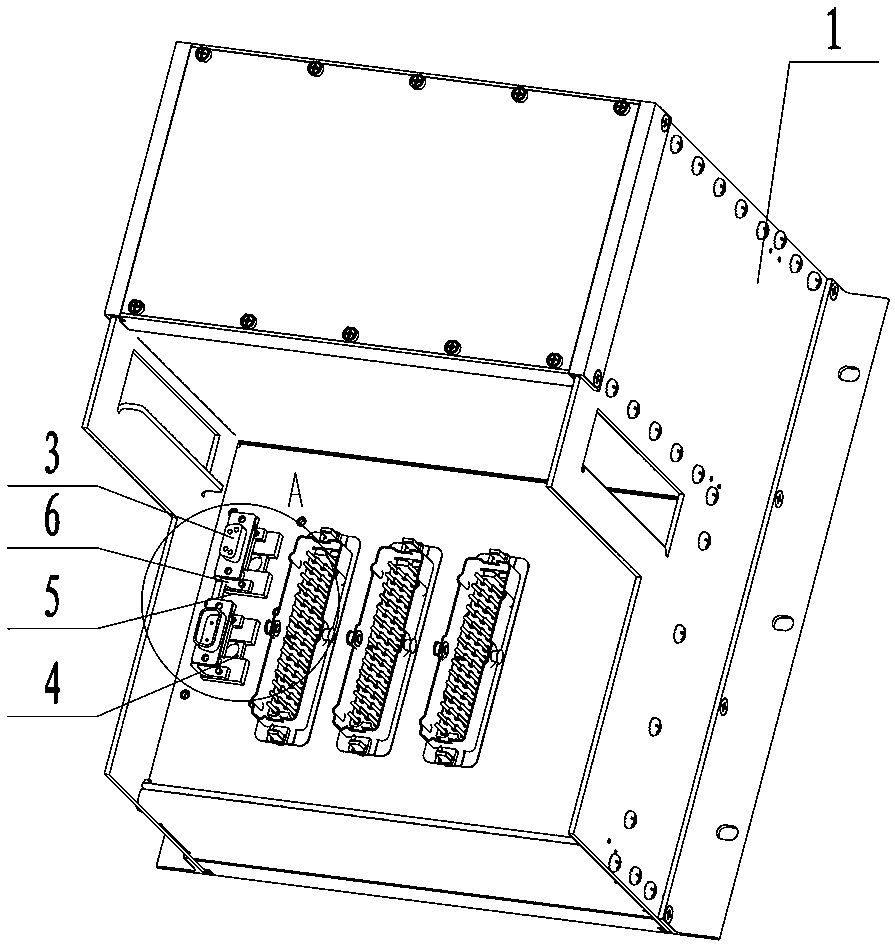
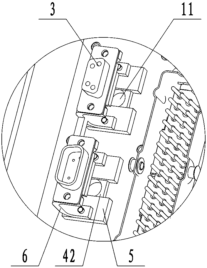
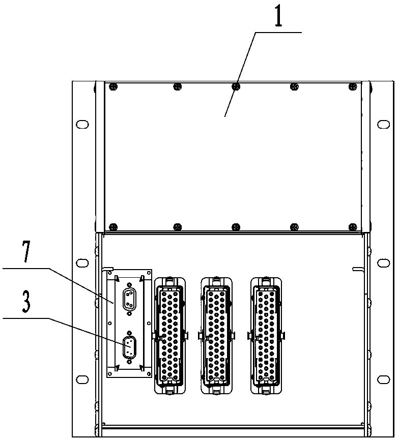
[0026] Such as Figure 1 to Figure 8 As shown, the chassis with electromagnetic shielding function of this embodiment includes a shielding box 1, a cable assembly 2 and a connector 3, the connector 3 is used to connect and communicate with the external equipment of the shielding box 1, and the connector 3 is connected to the cable The output end of the component 2 is connected, the shielding layer 21 of the cable component 2 is provided with a flange component 4, and the flange component 4 is sleeved on the cable component 2 to realize the covering and sealing of the shielding layer 21 of the cable component 2 to prevent Electromagnetic leakage of the shielding layer 21, the shielding box 1 is provided with a through hole 11 through which the cable assembly 2 passes, and the flange assembly 4 is sealed and installed at the through hole 11, ...


PUM


Abstract

The invention provides a cabinet capable of electromagnetic shielding. The cabinet comprises a shielding cabinet body, a cable assembly and a connector, the connector is in connection and communication with external equipment of the shielding cabinet body, the connector is connected with the output end of the cable assembly, a shielding layer of the cable assembly is provided with a flange assembly which prevents the shielding layer from electromagnetic leakage, the shielding cabinet body is provided with through holes through which the cable assembly penetrates, and the flange assembly is mounted at the positions of the through holes in a sealed manner. The cabinet can prevent transmission signals from interference, and the installation position of the connector can be changed.

Description

technical field [0001] The invention relates to a vehicle-mounted chassis, in particular to a chassis with electromagnetic shielding function. Background technique [0002] The EBCU chassis (electropneumatic brake control chassis) on the subway is the brain of the brake control of the urban rail vehicle. The fast, accurate and effective transmission of signals is related to the timely, safe and reliable braking of the vehicle. Therefore, the entire EBCU chassis needs to be well Electromagnetic shielding prevents interference or becomes a source of interference. The EBCU chassis needs to communicate with the outside through connectors, and the commonly used connectors cannot meet the electromagnetic shielding requirements of the EBCU chassis. [0003] There are two main types of existing connectors (take the D-SUB connector as an example): one uses a connector with a shell, and the cable assembly is connected to the connector shell through a flange to realize the connection b...

Claims


Application Information

Patent Timeline
Patent Type & Authority Patents(China)
IPC IPC(8): H01R13/6581
Inventor 刘文锋钱华谢永清余接任段炼
Owner ZHUZHOU CSR TIMES ELECTRIC CO LTD
Why Eureka
Try Eureka