Positioning method and system for shielding shell hole seam position

A shielding shell and positioning system technology, applied in the field of optical detection, can solve the problems of radiation leakage, not being improved enough, affecting the normal use of electronic equipment, etc., and achieve the effect of rapid positioning and preventing electromagnetic leakage

Active Publication Date: 2014-04-16
BEIJING CHOICE ELECTRONICS TECH CO LTD
View PDF5 Cites 3 Cited by
  • Summary
  • Abstract
  • Description
  • Claims
  • Application Information

AI Technical Summary

Problems solved by technology

However, after the electromagnetic radiation is diffracted by the holes, it is strengthened due to the coherent superposition of the waves, which produces special effects different from those expected by the shielding design and affects the normal use of electronic equipment.
[0003] At present, the near-field probe is usually used to detect the holes of the shielding shell, but often after finding the leak point and carrying out shielding treatment, it is found that the radiation leakage has not been improved enough. The reason is that the leak point is a tiny hole. The frequency of electromagnetic waves leaked from holes can reach 400GHz, while the current near-field probes can only detect electromagnetic waves in the frequency range of 30MHz-6GHz

Method used


Image

  • Positioning method and system for shielding shell hole seam position
  • Positioning method and system for shielding shell hole seam position

Examples


Embodiment Construction

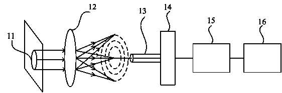
[0021] In order for those skilled in the art to better understand the technical solution of the present invention, firstly, the principle of the present invention is briefly introduced. The far-field diffraction formed by the electromagnetic radiation from the aperture of the shielding shell of electronic equipment is Fraunhofer diffraction. When the electromagnetic wave passes through the aperture, the central bright spot of the diffraction pattern, that is, the Airy disk, is the brightest and the energy of the electromagnetic wave is the largest. The largest position can locate the position of the aperture of the shielding shell. The positioning method and positioning system for the position of the aperture of the shielding case provided by the present invention will be described in detail below with reference to the accompanying drawings.

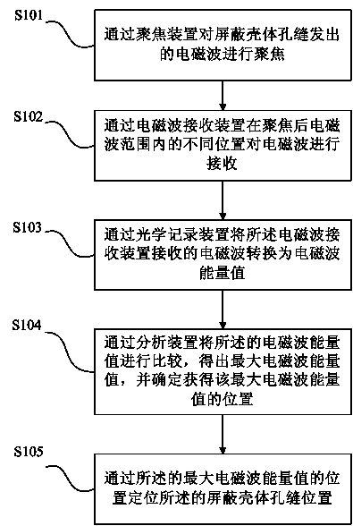
[0022] figure 1 It is a flow chart of the positioning method for the position of the aperture of the shielding shell provided by the p...


PUM


Abstract

The invention provides a positioning method and system for a shielding shell hole seam position. The positioning method for the shielding shell hole seam position includes the step S101 of focusing on electromagnetic waves transmitted by the shielding shell hole seam through a focusing device, the step S102 of receiving electromagnetic waves in different positions within the focused electromagnetic wave range through an electromagnetic wave receiving device, the step S103 of converting the electromagnetic waves received by the electromagnetic wave receiving device into electromagnetic energy values through an optical recording device and recording the electromagnetic energy values, the step S104 of comparing the electromagnetic energy values through an analysis device to obtain the maximum electromagnetic energy value and determining the position of the obtained maximum electromagnetic energy value, and the step S105 of locating the shielding shell hole seam position through the position of the maximum electromagnetic energy value. According to the positioning method and system for shielding shell hole seam position, micro-hole seams can be accurately positioned, and electromagnetic leakage of a shielding shell can be effectively prevented.

Description

technical field [0001] The invention relates to the field of optical detection, in particular to a positioning method and a positioning system for the positions of apertures in shielding shells. Background technique [0002] Electronic devices are often interfered by electromagnetic waves during use. In order to protect electronic devices from internal or external electromagnetic interference, shielding measures are usually taken for electronic devices. Large systems can be placed in shielded rooms or buildings with shielding measures, and small electronic devices are generally shielded electromagnetically through shielded enclosures. However, there are generally holes and slits unavoidably on the shielding case, either for the connection of power lines and signal lines, or for practical needs such as ventilation. Electromagnetic leakage from the holes in the shielding shell will constitute electromagnetic disturbance to other things in the system and cause electromagnetic ...

Claims


Application Information

Patent Timeline
Patent Type & Authority Applications(China)
IPC IPC(8): G01S11/06
CPCG01S1/00G01S11/06
Inventor 刘树海白同云徐峰
Owner BEIJING CHOICE ELECTRONICS TECH CO LTD
Why Eureka
Try Eureka