Puncture device

A puncture needle and biological technology, which can be used in puncture needles, incontinence prevention devices, diagnosis, etc., and can solve problems such as infection, large invasion, and damage to the urethra

Inactive Publication Date: 2015-11-18
TERUMO KK
View PDF8 Cites 1 Cited by
  • Summary
  • Abstract
  • Description
  • Claims
  • Application Information

AI Technical Summary

Problems solved by technology

[0004] However, if the vagina is incised, there is a possibility that the sling may be exposed into the vagina from the wound caused by the incision, or that complications such as infection from the wound may occur.
In addition, it has the following disadvantages: since the vagina is incised, it is very invasive and imposes a great burden on the patient
In addition, there is a risk that the surgeon may injure the urethra with the scalpel during the operation, and the surgeon himself may injure the fingertips with the scalpel.

Method used


Image

  • Puncture device
  • Puncture device
  • Puncture device

Examples


no. 1 approach

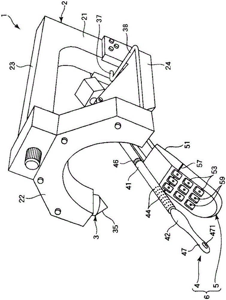
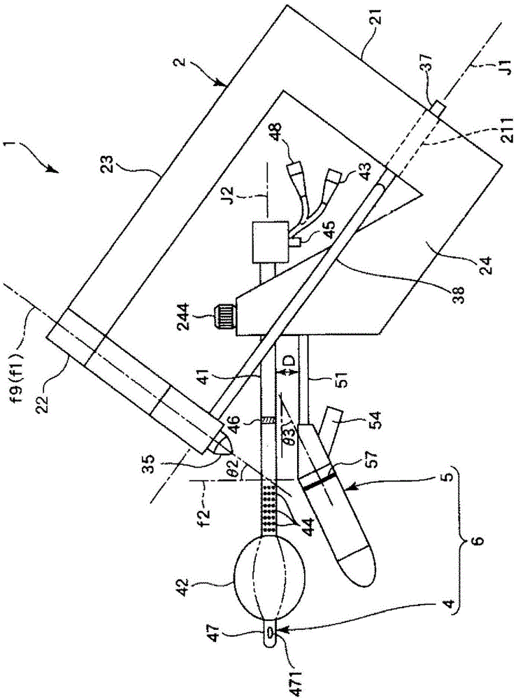
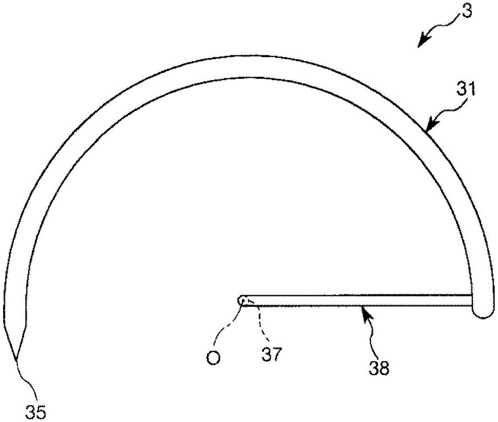
[0103] figure 1 It is a perspective view showing the first embodiment of the puncture device of the present invention. figure 2 Yes figure 1 Side view of the puncture device shown. image 3 Yes means figure 1 A top view of the puncture member included in the puncture device shown. Figure 4 Yes means figure 1 (A) is a perspective view, and (b) is a cross-sectional view taken along the line A-A in (a) of the diagram of the puncture member included in the puncture device shown. Figure 5 ~ Figure 7 Respectively means figure 1 A cross-sectional view of the guide portion of the frame included in the puncture device shown. Figure 8 Yes means figure 1 A plan view of the fixed portion of the frame provided in the puncture device shown. Picture 9 Yes figure 1 The shown puncture device has a side view of the inserter. Picture 10 It is a diagram showing the positional relationship between the puncture member and the obturator (pelvis), (a) is a side view, and (b) is a front view. Pictur...

no. 2 approach

[0183] Figure 21 It is a cross-sectional view of the puncture member of the puncture device (second embodiment) of the present invention.

[0184] Hereinafter, the second embodiment of the puncture device of the present invention will be described with reference to this figure, but the description will be centered on the differences from the foregoing embodiment, and description of the same matters will be omitted.

[0185] This embodiment is the same as the above-mentioned first embodiment except that the structure of the puncture member is different.

[0186] Such as Figure 21 As shown, the puncture needle 31 is composed of a combination of a tubular hollow body 311 having a hollow part 312 and an implant 9 housed in the hollow part 312. At the tip of the hollow portion 312, there is a needle tip portion 93 that can be attached and detached.

[0187] The implant 9 is connected to the needle tip portion 93 via a band 912 at the distal end portion of the implant body 91. The top of...

no. 3 approach

[0192] Figure 22 ~ Figure 24 Each is a diagram for explaining the operating procedure of the puncture device (third embodiment) of the present invention.

[0193] Hereinafter, the third embodiment of the puncture device of the present invention will be described with reference to these drawings, but the description will be centered on differences from the foregoing embodiment, and descriptions of the same matters will be omitted.

[0194] This embodiment is the same as the second embodiment except that the structure of the piercing member is different.

[0195] As an operation procedure of the puncture device 1 of the present embodiment, first, the puncture device 1 is set in the mounted state in the same manner as in the first embodiment described above.

[0196] Then like Figure 22 As shown, the puncture needle 31 is rotated counterclockwise in the figure. Thereby, the needle tip 93 penetrates the biological surface 1500 of the patient's right groin part or its vicinity and enters...


PUM


Abstract

This puncture device (1) has an arcuately curved puncture needle (31) which is supported so as to allow rotation with axis (J1) as the rotation center and which has a needle tip which punctures the body by rotating, a urethral insertion member (4) which has a linear-shape urethral insertion unit (41) which is inserted into the urethra, and a frame (2) which can link the puncture needle (31) and the urethral insertion member (4) and which rotatably supports the puncture needle, wherein the trajectory of the tip of the puncture needle (31) (plane (f9)) when the puncture needle rotates is inclined at an inclination angle (θ2) of 20°-60° with respect to the plane (f2) normal to the urethral insertion unit (41).

Description

Technical field [0001] The invention relates to a puncture device Background technique [0002] If you suffer from urinary incontinence, especially abdominal pressure urinary incontinence, abdominal pressure is applied during normal exercise or due to laughter, coughing, sneezing, etc., thereby causing urine leakage. The reasons for this include, for example, the pelvic floor muscle, which is the muscle supporting the urethra, is loosened due to childbirth. [0003] For the treatment of urinary incontinence, surgical therapies are effective. For example, a belt-shaped indwelling material for supporting biological tissues called "sling" is used, the sling is indwelled in the body and the sling is used to support the urethra (for example, refer to the patent Literature 1). For indwelling the sling in the body, the surgeon cuts the vagina with a scalpel, peels off between the urethra and the vagina, and uses a puncture needle or the like to connect the peeled part to the outside thr...

Claims


Application Information

Patent Timeline
Patent Type & Authority Applications(China)
IPC IPC(8): A61B17/34
CPCA61B17/06109A61B17/0482A61B17/06066A61B17/42A61B2017/00557A61B2017/00566A61B2017/00805A61B2017/06042A61B2017/06052A61B2019/4836A61M1/0088A61B2090/0807A61M1/87A61B17/3403A61B17/3468A61B2017/3405A61F2/0045A61F2002/0072
Inventor 川浦政克横井奈央有浦茂树
Owner TERUMO KK
Why Eureka
Try Eureka