Disposable pistol circumcision stapler

A circumcision and pistol-style technology, applied in surgery, medical science, surgical fixation nails, etc., can solve the problems of laborious operation, insufficient safety and reliability, etc., and achieve the effects of simplified structure, convenient operation, and improved success rate

Active Publication Date: 2016-11-30
JIANG XI YUAN SHENG LANG HE MEDICAL EQUIP
View PDF7 Cites 3 Cited by
  • Summary
  • Abstract
  • Description
  • Claims
  • Application Information

AI Technical Summary

Problems solved by technology

The above-mentioned patents have the defects of laborious operation and insufficient safety and reliability.

Method used


Image

  • Disposable pistol circumcision stapler
  • Disposable pistol circumcision stapler
  • Disposable pistol circumcision stapler

Examples


Embodiment Construction

[0026] In order to enable those skilled in the art to better understand the technical solution of the present invention, the present invention will be described in further detail below in conjunction with the accompanying drawings and specific embodiments. And the features in the embodiments can be combined with each other.

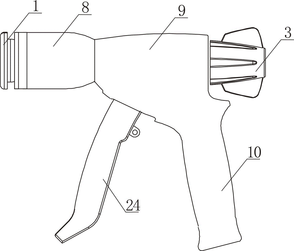
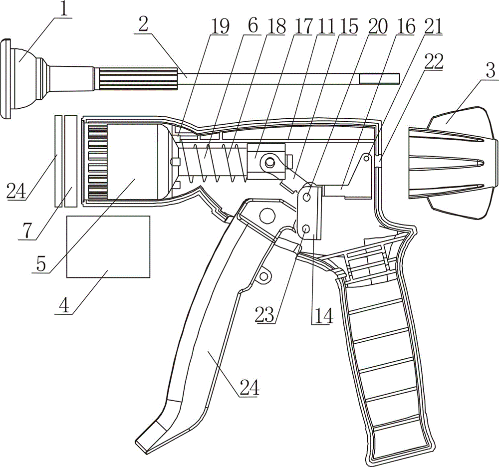
[0027] Such as figure 1 , 2 As shown, the disposable pistol-type circumcision stapler includes a glans seat 1, an adjustment rod 2, an adjustment handle 3, a cylindrical cutter 4, a staple ejector barrel 5, a hollow ejector rod 6, a staple bin ring 7 and For the staples arranged in the staple bin ring 7, the cylindrical cutter 4 is coaxially installed in the staple ejector tube 5, and also includes a gun body and a trigger transmission mechanism. The gun body is made of a tubular body. Part 8, the main shell part 9 and the handle part 10, the specific scheme is that the gun body is composed of two symmetrical halves, and each half part is integrally for...


PUM


Abstract

A disposable pistol type circumcision anastomat comprises a glans penis seat (1), a regulating lever (2), a regulating handle (3), a cylindrical cutter (4), a suturing nail ejection cylinder (5), a hollow ejector rod (6), a nail bin ring (7), and a suturing nail provided in the nail bin ring (7). The cylindrical cutter (4) is coaxially sleeved in the suturing nail ejection cylinder (5). The circumcision anastomat further comprises a gun body and a trigger drive mechanism. The gun body consists of a tubular body portion (8), a main housing portion (9), and a handle portion (10), the upper part of the main housing portion (9) being provided with a horizontal limiting plate (11). The trigger drive mechanism comprises a trigger (13), a drive member (14), a drive arm (15), a swing arm (16), a slide block (17), and a reset spring (18). Since the trigger drive mechanism is specially designed for cooperating with the horizontal limiting plate (11) in the gun body, the operation is more labor-saving and the displacement of the suturing nail ejection cylinder (5) is more accurate, thereby improving the success rates of circumcision and suturing.

Description

technical field [0001] The invention relates to a circumcision stapler, in particular to a disposable circumcision stapler. Background technique [0002] On August 4, 2010, the State Intellectual Property Office published a patent with a publication number of 201537118U and a patent name of a circumcision device. One end is connected with a bell-shaped glans seat, and the edge of the glans seat is provided with a cutter backing ring and a suture nail inverted foot ring, the other end of the pull rod is connected with the adjustment knob through the adjustment knob nut, and the top of the top cutting body is connected with a suture nail top column and a ring In the cutting knife, the end of the top cutting body is connected to a movable handle through a linkage push rod, the top of the top cutting body is matched with the bell-shaped glans seat, and the top of the casing is connected with a ring-shaped nail bin, and the ring-shaped nail bin is equipped with suture nails. The...

Claims


Application Information

Patent Timeline
Patent Type & Authority Patents(China)
IPC IPC(8): A61B17/326A61B17/115
CPCA61B17/326A61B17/115
Inventor 周明海刘晓鹏张小波黄燕李卫东
Owner JIANG XI YUAN SHENG LANG HE MEDICAL EQUIP
Why Eureka
Try Eureka