Smooth and self-adaptive valve screwing mechanical arm mechanism

A manipulator and self-adaptive technology, applied in the direction of manipulators, program-controlled manipulators, chucks, etc., can solve the problems of low efficiency of disaster relief operations, high operating costs, and inability to achieve tolerances, etc., to achieve improved practical value, low production costs, and saving material effect

Active Publication Date: 2015-11-25
HARBIN INST OF TECH
View PDF4 Cites 5 Cited by
  • Summary
  • Abstract
  • Description
  • Claims
  • Application Information

AI Technical Summary

Problems solved by technology

[0003] The purpose of the present invention is to solve the problem that the existing disaster relief robot cannot realize the end effector that has a tolerance to dock with the valve handwheel and realize the screwing of the valve, resulting in low disaster relief operation efficiency and high operation cost

Method used


Image

  • Smooth and self-adaptive valve screwing mechanical arm mechanism
  • Smooth and self-adaptive valve screwing mechanical arm mechanism
  • Smooth and self-adaptive valve screwing mechanical arm mechanism

Examples


specific Embodiment approach 1

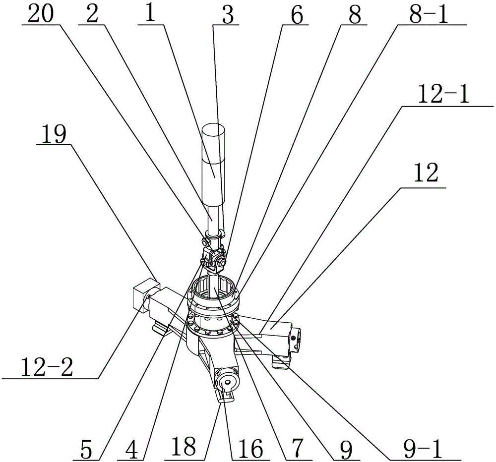
[0014] Specific implementation mode 1: Combine 1 to Figure 4 To explain this embodiment, a compliant and adaptive valve screwing manipulator mechanism of this embodiment includes a transmission mechanism, a tool interface mechanism, and a three-jaw manipulator. The transmission mechanism is connected to the three-jaw manipulator through the tool interface mechanism.

[0015] The transmission mechanism includes a servo motor 1, a spindle 2 and a Hooke hinge mechanism. The output end of the servo motor 1 is connected with the spindle 2, and the spindle 2 is provided with a Hooke hinge mechanism;

[0016] The tool interface mechanism includes a connecting end 8 and a tool interface 9. The tool interface 9 is mounted on the three-jaw manipulator, and the connecting end 8 is mounted on the tool interface 9;

[0017] The three-jaw manipulator includes a manipulator base 12, a large bevel gear 13, three small bevel gears 14, three lead screws 15, three lead screw bases 16, a mechanical fing...

specific Embodiment approach 2

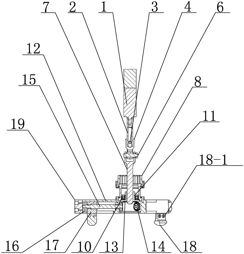
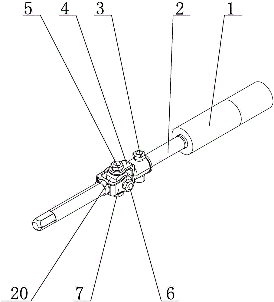
[0021] Specific implementation manner two: combination figure 1 , figure 2 with image 3 To illustrate this embodiment, the Hooke hinge mechanism of this embodiment includes a cross shaft outer ring 4, a central shaft 5, a bolt shaft 6, a cross shaft inner ring 7, a cross shaft 20, and a plurality of hexagon socket head screws 3, and the cross shaft outer ring The ring 4 is connected to the spindle 2 by a plurality of hexagon socket head screws 3, the two ends of the cross shaft 20 in the vertical direction are matched with the outer ring 4 of the cross shaft by two hexagon socket head screws 3, the bolt shaft 6 It is installed horizontally on the cross shaft 20, one end of the cross shaft inner ring 7 is connected to both ends of the bolt shaft 6, and the other end of the cross shaft inner ring 7 is connected to the mandrel 2. The above parts constitute the Hooke hinge mechanism. The Hooke hinge mechanism can realize the small-angle deflection of the output end, and the maximu...

specific Embodiment approach 3

[0022] Specific implementation mode three: combination figure 1 with figure 2 To explain this embodiment, the three-jaw manipulator of this embodiment further includes a counterweight iron 19 installed on the outside of any one of the claw bases on the manipulator base 12. Movement is more flexible. The other composition and connection relationship are the same as in the second embodiment.


PUM

PropertyMeasurementUnit
Angleaaaaaaaaaa

Abstract

The invention relates to a valve screwing mechanical arm mechanism, in particular to a smooth and self-adaptive valve screwing mechanical arm mechanism which aims at solving the problems that an existing disaster relief robot cannot be in butt joint with a valve hand wheel with tolerance, and a tail end executer for screwing a valve cannot be achieved, so that the disaster relief operating efficiency is low, and the operating cost is high. The output end of a servo motor is connected with a core shaft. The core shaft is provided with a hook joint mechanism. A tool connector piece is installed on a three-pawl mechanical arm. Three bevel pinions are installed in a center pawl base in a mechanical arm base. A large bevel gear is installed at the upper end of the middle of the mechanical arm base. The core shaft is inserted in the large bevel gear. A lead screw base is arranged in each pawl base. One end of each lead screw is connected with the corresponding lead screw base. The other end of each lead screw is connected with the corresponding bevel pinion. A mechanical finger is installed on one lead screw and is in sliding connection with one pawl base, and two fingers are installed on the other two lead screws respectively. The valve screwing mechanical arm mechanism is suitable for a screw screwing mechanism capable of being in smooth butt joint with the valve hand wheel.

Description

Technical field [0001] The invention relates to a valve screwing manipulator mechanism, in particular to a compliant self-adapting valve screwing manipulator mechanism. Background technique [0002] Facing the urgent needs of the country for accident prevention and rescue of nuclear power plants and the technological development trend of emergency rescue robots for nuclear power plants, some high-calibration domestic rescue robots have started research on nuclear power plants. In the case of leakage in the nuclear power plant and people unable to enter the nuclear power plant for operation, the disaster relief robot urgently needs an end effector that can realize the tolerance of the valve handwheel and realize the screwing of the valve. The valve actuator can also be screwed when it is not high, which leads to the problems of low efficiency and high operating cost of existing disaster relief operations. Summary of the invention [0003] The purpose of the present invention is to...

Claims


Application Information

Patent Timeline
IPC IPC(8): B25J9/00B25J9/12B25J15/10B25J19/00
Inventor 刘振邓宗全邢宏军周建超陈明马常友高海波丁亮
Owner HARBIN INST OF TECH
Why Eureka
Try Eureka