A Compliant Docking Device for Robotic Arm Based on Double Hooke Hinge Mechanism

A technology of a docking device and a manipulator, which is applied in the directions of manipulators, program-controlled manipulators, manufacturing tools, etc., can solve the problems of difficult to protect the docking device, large contact force of the mechanism, complicated control, etc., and achieves simple structure, small docking contact force, and storage. The effect of process safety

Active Publication Date: 2016-10-19
HARBIN INST OF TECH
View PDF8 Cites 0 Cited by
  • Summary
  • Abstract
  • Description
  • Claims
  • Application Information

AI Technical Summary

Problems solved by technology

[0003] The purpose of the present invention is to solve the problem that the existing docking device has complex control and relatively large mechanism contact force, which makes it difficult to protect the docking device, and further provides a compliant docking device for mechanical arms based on a double Hooke hinge mechanism

Method used


Image

  • A Compliant Docking Device for Robotic Arm Based on Double Hooke Hinge Mechanism
  • A Compliant Docking Device for Robotic Arm Based on Double Hooke Hinge Mechanism
  • A Compliant Docking Device for Robotic Arm Based on Double Hooke Hinge Mechanism

Examples


specific Embodiment approach 1

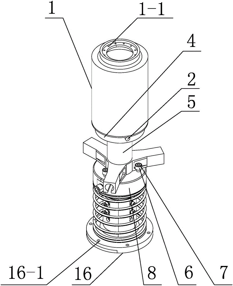
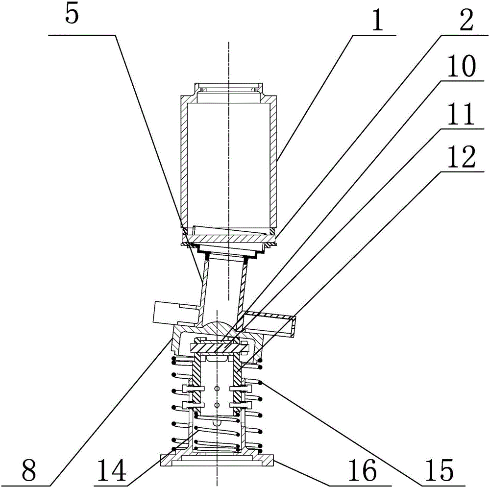
[0012] Specific embodiment one: combine 1 to Figure 7 Describe this embodiment. A compliant docking device for a robotic arm based on a double Hooke hinge mechanism in this embodiment includes an end effector of the robotic arm and a storage device for the end effector. The end effector of the robotic arm is installed on the upper end of the storage device for the end effector. ,

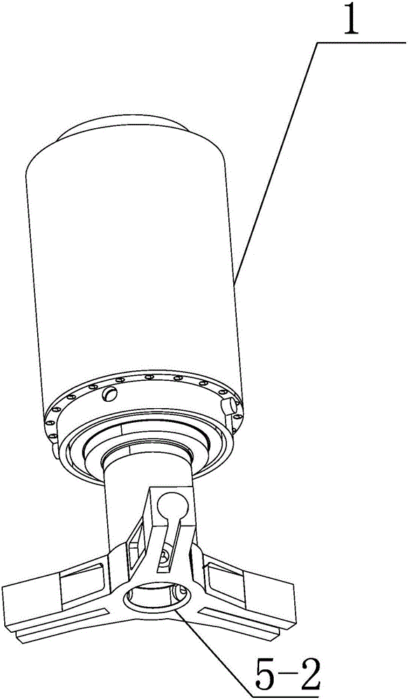
[0013] The end effector of the mechanical arm includes a first connecting piece 1, a first cross shaft 2, an inner ring 3, an outer ring 4 and a tool joint 5. The upper end of the first connecting piece 1 is connected to the external mechanical arm through a connecting hole 1-1. The first cross shaft 2 is installed on the upper part of the tool joint 5, the inner ring 3 is installed on the inner side wall of the upper end of the tool joint 5, the outer ring 4 is installed on the upper outer side wall of the tool joint 5, and the lower end of the first connector 1 passes through the outer ring 4 Co...

specific Embodiment approach 2

[0018] Specific implementation mode two: combination Figure 1 to Figure 4 To illustrate this embodiment, the tool joint 5 of this embodiment includes a column and three connecting arms, and different tools can be placed in the connecting arms to realize different functions. The three connecting arms are evenly connected to the lower end of the column, a spherical groove 5-2 is provided at the center of the bottom end where the three connecting arms meet, and a groove 5-2 is provided on both sides of each connecting arm. 1. The groove 5-2 can realize the cooperation with the hemispherical protrusion 8-1 on the top of the connecting seat 8 to realize the positioning of the end effector; Clamp it tightly so that the robotic arm can be disengaged from the end effector. Other compositions and connections are the same as in the first embodiment.

specific Embodiment approach 3

[0019] Specific implementation mode three: combination Figure 5 Describe this embodiment, the Hooke hinge mechanism of this embodiment also includes 3 locking sleeves 6 and 3 first screws 7, 3 first screws 7 are installed on the connection seat 8, and each first screw 7 is set There is a locking sleeve 6. The first screw 7 fastens the locking sleeve 6 connected thereto on the connecting base 8 . When the mechanical arm is disengaged from the end effector, the locking sleeve 6 can be clamped to the groove 5-1 to facilitate the disengagement of the mechanical arm from the end effector. Other compositions and connections are the same as those in the second embodiment.


PUM


Abstract

The invention relates to a hooke joint butt joint device, in particular to a mechanical arm flexible butt joint device based on a double-hooke-joint mechanism. The device aims at solving the problems that an existing butt joint device is complex in control and large in mechanism contact force and is not easily protected. A mechanical arm end effector is installed at the upper end of an end effector storage device, the upper end of a connecting piece (1) is connected with an external mechanical arm through a connecting hole (1-1), a first cross shaft (2) is installed at the upper portion of a joint connector (5), an inner ring (3) is installed on the inner side wall of the upper end of the tool joint (5), an outer ring (4) is installed on the outer side wall of the upper end of the tool joint (5), and the lower end of the connecting piece (1) is connected with the tool joint (5) through the outer ring (4). The end effector storage device comprises the hookie-joint mechanism and a buffering reset mechanism. The hooke-joint mechanism is installed on the buffering reset mechanism. The mechanical arm flexible butt joint device is suitable for butt joint of mechanical structures in space.

Description

technical field [0001] The invention relates to a double Hookee hinge docking device, in particular to a compliant docking device for a mechanical arm. Background technique [0002] During the working process of the robotic arm, it will inevitably involve the docking problem of different mechanisms. The docking mechanism not only has a wide range of applications on the ground, but also plays an important role in the weightless environment of spaceflight. The rigid docking technology requires high precision of the robotic arm, and due to contact force and other reasons, it is easy to cause damage to the docking mechanism. The existing docking device requires high precision of the robotic arm, and the docking function is realized by actively controlling the robotic arm. The control is complex and the contact force of the mechanism is relatively large, so it is difficult to protect the docking device. Contents of the invention [0003] The purpose of the present invention i...

Claims


Application Information

Patent Timeline
Patent Type & Authority Patents(China)
IPC IPC(8): B25J9/00
Inventor 高海波丁亮马常友邓宗全周建超邢宏军陈明陶建国
Owner HARBIN INST OF TECH
Why Eureka
Try Eureka