A Compliant Adaptive Valve Screwing Manipulator Mechanism
A manipulator and self-adaptive technology, applied in the direction of manipulators, program-controlled manipulators, chucks, etc., can solve the problems of inability to achieve tolerance, low efficiency of disaster relief operations, and high operating costs, so as to save materials, improve practical value, and lower production costs Effect
- Summary
- Abstract
- Description
- Claims
- Application Information
AI Technical Summary
Problems solved by technology
Method used
Image
Examples
specific Embodiment approach 1
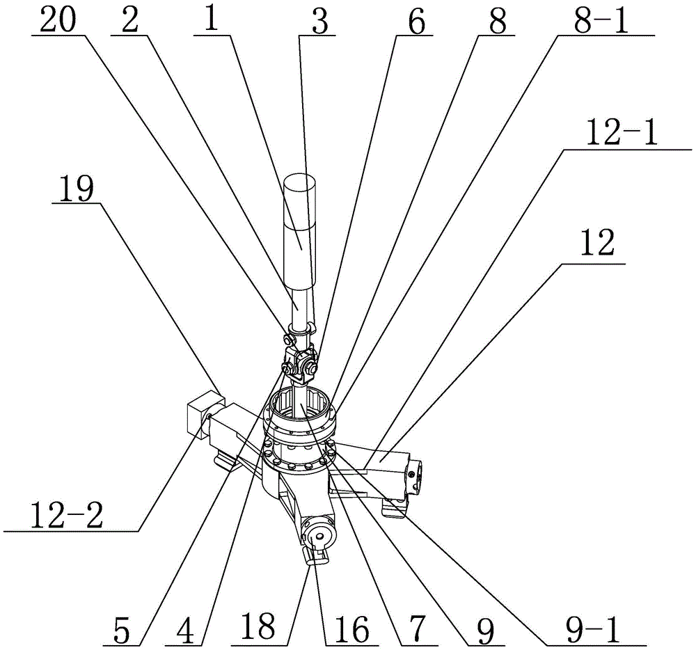
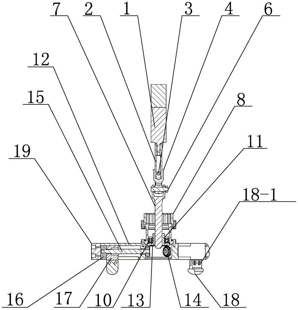
[0014] Specific embodiment one: combine 1 to Figure 4 Describe this embodiment. A compliant and adaptive valve screwing manipulator mechanism in this embodiment includes a transmission mechanism, a tool interface mechanism and a three-claw manipulator. The transmission mechanism is connected to the three-claw manipulator through the tool interface mechanism.
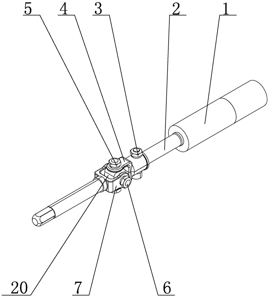
[0015] The transmission mechanism includes a servo motor 1, a mandrel 2 and a Hooke hinge mechanism, the output end of the servo motor 1 is connected to the mandrel 2, and the mandrel 2 is provided with a Hooke hinge mechanism;
[0016] The tool interface mechanism includes a connection end 8 and a tool interface piece 9, the tool interface piece 9 is installed on the three-jaw manipulator, and the connection end 8 is installed on the tool interface piece 9;
[0017] The three-claw manipulator includes a manipulator seat 12, a large bevel gear 13, three small bevel gears 14, three lead screws 15, three lead screw seats ...
specific Embodiment approach 2
[0021] Specific implementation mode two: combination figure 1 , figure 2 and image 3 Describe this embodiment, the Hooke hinge mechanism of this embodiment comprises cross shaft outer ring 4, central shaft 5, bolt shaft 6, cross shaft inner ring 7, cross shaft 20 and a plurality of hexagon socket cap screws 3, outside cross shaft The ring 4 is connected to the mandrel 2 through a plurality of hexagon socket head screws 3, and the two ends of the cross shaft 20 in the vertical direction are matched with the outer ring 4 of the cross shaft through two hexagon socket head screws 3, and the bolt shaft 6 Horizontally pierced on the cross shaft 20 , one end of the cross shaft inner ring 7 is connected with both ends of the bolt shaft 6 , and the other end of the cross shaft inner ring 7 is connected with the mandrel 2 . The above parts form the Hooke hinge mechanism, which can realize the small angle deflection of the output end, and the maximum deflection angle can reach 5°~10°...
specific Embodiment approach 3
[0022] Specific implementation mode three: combination figure 1 and figure 2 The present embodiment is described. The three-claw manipulator of the present embodiment further includes a counterweight iron 19 , and the counterweight iron 19 is installed on the outside of any claw seat on the manipulator seat 12 . Movement is more flexible. Other compositions and connections are the same as those in the second embodiment.
PUM
 Abstract
Description
Claims
Application Information
 - R&D
- Intellectual Property
- Life Sciences
- Materials
- Tech Scout
- Unparalleled Data Quality
- Higher Quality Content
- 60% Fewer Hallucinations
Browse by: Latest US Patents, China's latest patents, Technical Efficacy Thesaurus, Application Domain, Technology Topic, Popular Technical Reports.
© 2025 PatSnap. All rights reserved.Legal|Privacy policy|Modern Slavery Act Transparency Statement|Sitemap|About US| Contact US: help@patsnap.com


