Swing arm feeding device

A feeding device, swing arm type technology, applied in the field of swing arm type feeding device, can solve the problems of manual installation of raw materials, high production cost, complex structure, etc., to save the loading machine, simplify the structure, save Institutional Effects

Inactive Publication Date: 2017-08-15
王根乐
View PDF13 Cites 0 Cited by
  • Summary
  • Abstract
  • Description
  • Claims
  • Application Information

AI Technical Summary

Problems solved by technology

[0003] The invention provides a swing arm type feeding device, which solves the problems of manual installation of raw materials, complicated structure, high energy consumption and high production cost in the prior art.

Method used


Image

  • Swing arm feeding device
  • Swing arm feeding device
  • Swing arm feeding device

Examples


Embodiment Construction

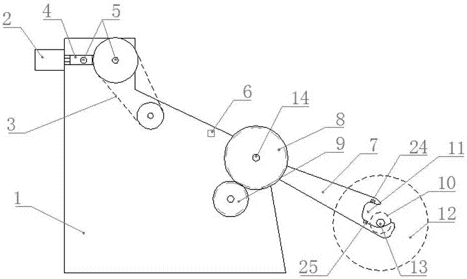
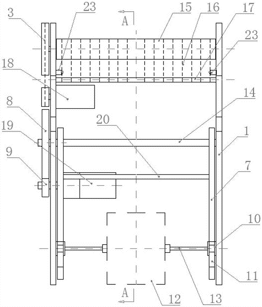
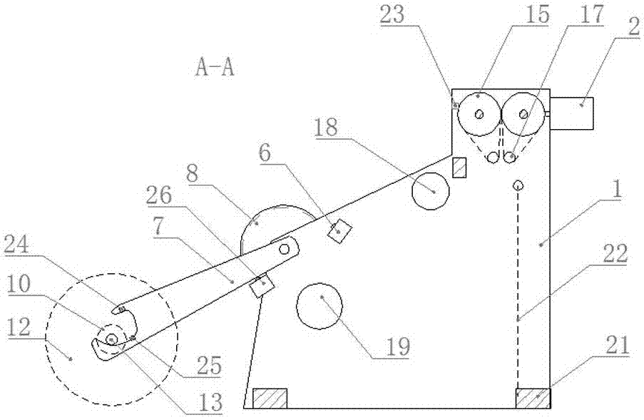
[0020] like Figure 1-Figure 9 As shown, a feeding device for a swing arm type bag making machine in the present invention includes a bracket 1 on which a pair of rubber rollers 15 are mounted, and the rubber roller shaft 5 of one of the rubber rollers 15 is connected to the The rubber roller driving motor 18 on the support 1 is connected by transmission, and it is characterized in that the rear end of the support 1 is hinged with one end of a pair of swing arms 7 through a drive shaft 14, and the other end of the swing arm 7 is provided with an opening Upward groove 11; the drive shaft 14 is rotationally connected to the bracket 1 and is fixedly connected to the swing arm 7, and one end of the drive shaft 14 is connected to the swing arm drive motor 19 mounted on the bracket 1 through a gear transmission mechanism; A roller 10 is respectively housed at both ends of the raw material shaft 13 .

[0021] The width of the bottom of the groove 11 on the swing arm 7 leaves space f...


PUM


Abstract

A swing arm type feeding device includes a bracket on which a pair of rubber rollers are mounted, and the rubber roller shaft of one of the rubber rollers is connected to the rubber roller drive motor installed on the bracket through a synchronous belt mechanism. It is characterized in that, The rear end of the bracket is hinged with one end of a pair of swing arms through a drive shaft, and a groove with an opening facing upward is provided at the other end of the swing arm; the drive shaft is rotationally connected with the bracket, and is fixedly connected with the swing arm , one end of the drive shaft is connected to the swing arm drive motor installed on the bracket through a gear transmission mechanism; a roller is installed at both ends of the raw material shaft. The beneficial effects of the present invention are: labor saving for loading materials; low energy consumption; simple structure and reduced manufacturing cost; through the longer groove and the position switches on both sides of the groove, combined with the infrared sensor and the upper limit of the swing arm The switch can control the swing arm to swing gradually to avoid impact damage to the rubber roller caused by excessive swing range.

Description

technical field [0001] The invention relates to a swing arm type feeding device, which is used for feeding a bag making machine, and the bag making machine includes a plastic bag making machine. Background technique [0002] The raw material of the bag making machine for making plastic bags is a cylindrical film (or sheet) rolled on a tubular shaft. When in use, the rolled raw material is lifted and placed on the bracket at the rear of the bag making machine. The disadvantage of this feeding method is that it is very laborious to manually install the raw materials. If the machine is used, it will not only take up space, but also increase the cost; because the bag making machine does not feed at a constant speed, it has to stop at equal intervals, so in order to avoid the raw material coils in the feeding In the process, the plastic film is curled and overlapped, and the raw material film needs to pass through multiple rollers alternately, and a free deflection mechanism is u...

Claims


Application Information

Patent Timeline
Patent Type & Authority Patents(China)
IPC IPC(8): B31B50/10
Inventor 王根乐
Owner 王根乐
Why Eureka
Try Eureka