A supporting loading device for loading and unloading building materials

A loading device and building material technology, applied in the direction of loading/unloading, transportation and packaging, rollers, etc., can solve the problems of falling, easy shaking, lack of fixing mechanism for goods, etc., and achieve the effect of reducing shaking and reducing friction

Active Publication Date: 2021-07-02
重庆欧克斯防水保温工程有限公司
View PDF8 Cites 0 Cited by
  • Summary
  • Abstract
  • Description
  • Claims
  • Application Information

AI Technical Summary

Problems solved by technology

[0004] The purpose of the present invention is to solve the disadvantages in the prior art that the loading and unloading is laborious, the cargo lacks a fixing mechanism, and it is easy to shake and cause falling during transportation, and proposes a supporting loading device for loading and unloading of building materials

Method used


Image

  • A supporting loading device for loading and unloading building materials
  • A supporting loading device for loading and unloading building materials
  • A supporting loading device for loading and unloading building materials

Examples


Embodiment 1

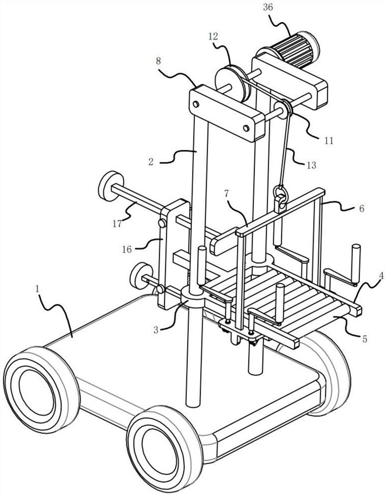
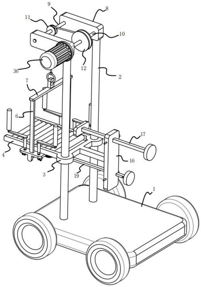
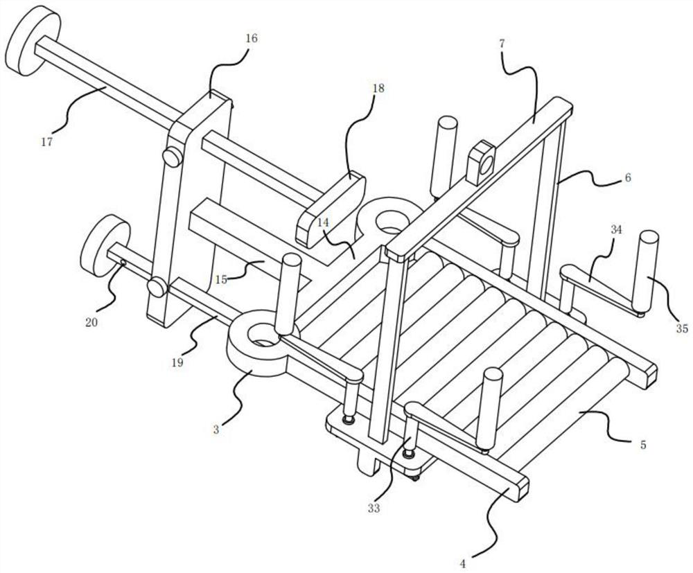
[0022] refer to Figure 1-7 , a support loading device for loading and unloading building materials, including a walking platform 1, the walking platform 1 can be a flatbed truck driven by electricity. The upper surface of the walking platform 1 is fixedly equipped with two corresponding vertical bars 2, and each vertical bar 2 is equipped with a movable sleeve 3, and a horizontal bar 4 is fixedly connected to the two movable sleeves 3, and two The crossbars 4 are arranged parallel to each other, and several roller bodies 5 are installed between the two crossbars 4 at equal intervals along the length direction. Connecting rod 15, vertical plate 16 is fixedly installed on the outer end of connecting rod 15, and a driving mechanism is installed on the upper part of vertical plate 16, and a driving mechanism is fixedly installed on the bottom of vertical plate 16, and a driving mechanism is fixedly installed on the lower surface of two cross bars 4. The cargo fixing mechanism co...

Embodiment 2

[0026] refer to Figure 1-7 , as another preferred embodiment of the present invention, the difference from Embodiment 1 is that the driving mechanism includes a second insertion rod 19, an insertion hole 20, and a second insertion rod 19 and a rack 21 are provided through the lower part of the riser 16. A rack 21 is fixedly connected to the inner end of the second insertion rod 19 , and a plurality of insertion holes 20 are opened on the second insertion rod 19 .

[0027] The cargo fixing mechanism includes a fixed plate 22, a horizontal plate 23, a rotating shaft 24, a gear 25, a rectangular block 26, a curved bar 27, a movable block 28, a connecting rod 29, a connecting plate 30, a vertical plate 31, a guide rod 32, a movable rod 33, Plate 34, cylinder 35, a fixed plate 22 is fixedly installed on the lower surfaces of the two cross bars 4, a horizontal plate 23 is fixedly installed between the two fixed plates 22, and a rotating shaft is rotatably installed in the middle of...

Embodiment 3

[0030] refer to Figure 1-2 , as another preferred embodiment of the present invention, the difference from Embodiment 1 is that the winding mechanism includes a side plate 8, a first fixed shaft 9, a second fixed shaft 10, a guide wheel 11, a winding wheel 12, and a cable 13 , a side plate 8 is fixedly installed on the top ends of the two vertical bars 2, and a first fixed shaft 9 and a second fixed shaft 10 arranged in parallel are fixedly installed between the two side plates 8, and the first fixed shaft 9 and the top plate 7 Correspondingly arranged, on the first fixed shaft 9, a guide wheel 11 is rotatably installed, and on the second fixed shaft 10, a winding wheel 12 is rotatably installed, and one end of the cable 13 is fixedly wound on the winding wheel 12, and the other end of the cable 13 is After passing through the guide wheel 11, it is fixedly connected on the top plate 7.

[0031] By controlling the winding motor 35 to wind up the cable 13, the height of the to...


PUM


Abstract

The invention relates to the technical field of building material loading and unloading, in particular to a supporting loading device for building material loading and unloading, which includes a walking platform, and a cross bar is fixedly connected to two movable sleeves, and the two cross bars are arranged parallel to each other. A number of roller bodies are installed at equal intervals along the length direction, and the two movable sleeves are fixedly connected by a connecting plate. A connecting rod is fixedly installed on the outer surface of the connecting plate, and a vertical plate is fixedly installed on the outer end of the connecting rod. A push mechanism is installed, a drive mechanism is fixedly installed on the lower part of the vertical plate, a cargo fixing mechanism connected with the drive mechanism is fixedly installed between the lower surfaces of the two cross bars, and a support plate is fixedly installed on the upper surfaces of the two cross bars. A top plate is fixedly installed between the two support plates, and a winding mechanism is fixedly installed between the top ends of the two vertical rods, and the winding mechanism is connected to the top plate through transmission. The invention has the advantages of speed block for cargo loading and unloading, more convenient and labor-saving.

Description

technical field [0001] The invention relates to the technical field of building material loading and unloading, in particular to a supporting loading device for building material loading and unloading. Background technique [0002] Building materials are a general term for materials used in civil engineering and construction engineering. It can be divided into structural materials, decorative materials and some special materials. Structural materials include wood, bamboo, stone, cement, concrete, metal, brick, ceramics, glass, engineering plastics, composite materials, etc. Decorative materials include various coatings, paints, coatings, veneers, tiles of various colors, glass with special effects, etc.; special materials refer to waterproof, moisture-proof, anti-corrosion, fire-proof, flame-retardant, sound insulation, heat insulation, heat preservation, sealing, etc. [0003] In the cargo storage workshops of some small-scale building material retailers, since they canno...

Claims


Application Information

Patent Timeline
Patent Type & Authority Patents(China)
IPC IPC(8): B65G67/30B65G13/00B65H75/38
CPCB65G13/00B65G67/30B65H75/38
Inventor 肖泽东
Owner 重庆欧克斯防水保温工程有限公司
Why Eureka
Try Eureka