

Unmanned aerial vehicle flight control method and device
A technology for flight control and unmanned aerial vehicles, which is applied in the directions of power units, aircraft parts, transportation and packaging on aircraft, and can solve problems such as unmanned aerial vehicles being unable to fly smoothly.
Inactive Publication Date: 2015-11-25
SHENZHEN AEE AVIATION TECH
View PDF4 Cites 16 Cited by
- Summary
- Abstract
- Description
- Claims
- Application Information
AI Technical Summary
Problems solved by technology
[0005] The main purpose of the present invention is to provide a UAV flight control method and device, which aims to solve the technical problem that the UAV cannot fly smoothly in the prior art
Method used
View moreImage
Smart ImageViewing Examples

Examples
no. 1 example
[0103] Based on the first embodiment of the above-mentioned UAV flight control device, the device also includes:
[0104] The setting module 40 is used to preset the corresponding PID parameters of the UAV in each operating state.
[0105] The PID parameters corresponding to different operating states are different, and the PID parameters include P value, I value and D value. The PID parameters of the UAV in each operating state can be set according to the needs. For example, the PID parameters corresponding to the hovering state are set to P1, I1, and D1. Among them, the larger the P1, the faster the motor of the UAV will start from the current state. The speed is adjusted to the target speed.
Login to View More PUM
 Abstract
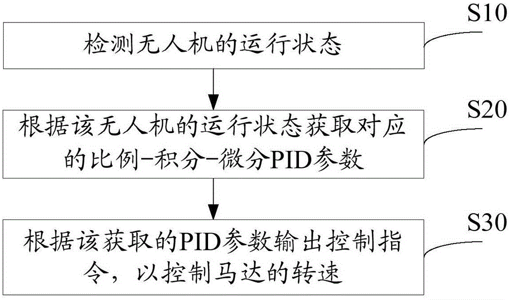
The invention discloses an unmanned aerial vehicle flight control method. The unmanned aerial vehicle flight control method comprises the steps of detecting a running state of an unmanned aerial vehicle, obtaining corresponding proportional integral differential (PID) parameters according to the running state of the unmanned aerial vehicle, outputting a control instruction according to the obtained PID parameters so as to control the rotation speed of a motor. The invention further discloses an unmanned aerial vehicle flight control device. By means of the unmanned aerial vehicle flight control method and device, the flight stability of the unmanned aerial vehicle can be improved.
Description
technical field [0001] The invention relates to the field of unmanned aerial vehicles, in particular to a method and device for controlling the flight of an unmanned aerial vehicle. Background technique [0002] Unmanned aerial vehicle (unmanned aerial vehicle) is a kind of aircraft that is gradually becoming practical at present. It has the advantages of flexible maneuverability, quick response, unmanned flight, and low operation requirements. It can complete the tasks performed by manned aircraft, and is more suitable for completing tasks that cannot be performed by manned aircraft, such as geological disaster investigation in dangerous areas. [0003] The power unit of the UAV mainly includes a motor and a controller that controls the rotation of the motor. In the prior art, when the motor speed is controlled by the controller, the same PID (proportion-integration-differentiation, proportional-integration-differentiation) control algorithm is used, that is, the same PID ...
Claims
Login to View More Application Information
Patent Timeline
 IPC IPC(8): B64D31/06
Inventor张显志
OwnerSHENZHEN AEE AVIATION TECH