
An infinite sliding sleeve and its process method

An infinite-stage, sliding-sleeve technology, applied in the direction of earthwork drilling, production fluid, wellbore/well components, etc., can solve the problem of increasing tool erosion, making it difficult to fully develop the potential of the production layer, and improving the work of the plunger pump of the operating crew Pressure and other issues to achieve the effect of reducing erosion, improving reliability and construction safety, and increasing scale

Active Publication Date: 2018-04-03
PETROCHINA CO LTD
View PDF11 Cites 0 Cited by
  • Summary
  • Abstract
  • Description
  • Claims
  • Application Information

AI Technical Summary

Problems solved by technology

[0005] Disadvantages of prior art 1: due to the classification method of ball seat classification, the grades that can be separated in oil pipes with a certain inner diameter are limited, and because the inner meridian of the ball seat becomes smaller and smaller from top to bottom, acidification is carried out at large displacements During the fracturing process, a large throttling pressure difference will be generated, which will inevitably increase the working pressure of the plunger pump of the operating vehicle group and increase the erosion of the tools. At the same time, it will also limit the increase in the operation scale and make it difficult to fully develop the production zone. potential

Method used


Image

  • An infinite sliding sleeve and its process method
  • An infinite sliding sleeve and its process method
  • An infinite sliding sleeve and its process method

Examples


Embodiment 1

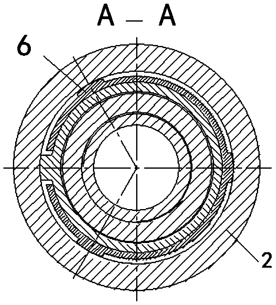
[0037] Embodiment 1: as figure 1 , figure 2 , image 3 , Figure 4 , Figure 5 , Figure 6As shown, it consists of coupling 1, body 2, displacement sliding sleeve 3, first O-ring 4, sliding sleeve shear pin 5, locking ring 6, second O-ring 7, fixing screw 8, lower joint 9, Claw-shaped displacement ball seat 10, sealing ball 11, V-shaped sealing ring 12, spacer ring 13, guiding and fixing ring 14 etc. are formed.

[0038] figure 1 State when the present invention enters the well, figure 2 Put into the sealing displacement mechanism that is made up of 10~14 and open the state when sliding sleeve when the present invention works.

[0039] Infinite grading is achieved like this: figure 1 As shown, the state of the present invention when entering the well is that the coupling 1 is connected to the body 2, and the body 2 has three symmetrical oblong holes. The sleeve 3 seals the oblong hole, the upper end of the displacement sliding sleeve 3 is processed with an annular g...

Embodiment 2

[0043] Embodiment 2: as figure 1 , figure 2 , image 3 , Figure 4 , Figure 5 , Figure 6 As shown, an infinite sliding sleeve consists of a coupling 1, a body 2, a displacement sliding sleeve 3, a first O-ring seal 4, a sliding sleeve shear pin 5, a locking ring 6, and a second O-ring 7, and is fixed Screw 8, lower joint 9, claw-shaped displacement ball seat 10, sealing ball 11, V-shaped sealing ring 12, spacer ring 13, guiding and fixing ring 14, etc. are composed.

[0044] The state when entering the well is that the coupling 1 is connected to the main body 2, the displacement sliding sleeve 3 is arranged in the main body 2, and the lower end of the main body 2 is connected with the lower joint 9.

[0045] The body 2 is provided with three oblong holes, and there are several discontinuous annular grooves in the lower part of the body 2 .

[0046] The body 2 is equipped with a displacement sliding sleeve 3 when entering the well, and the upper and lower ends of the d...

Embodiment 3

[0055] Embodiment 3: as figure 1 , figure 2 , image 3 , Figure 4 , Figure 5 , Figure 6 as shown,

[0056] An infinite-stage sliding sleeve can be divided into infinite stages in the same well, and the inner diameter of each stage of the sliding sleeve remains consistent, which can greatly reduce the frictional resistance of liquid flow and is beneficial to increase the processing scale.

[0057] The following is further optimization / and improvement to the technical solution of the present invention:

[0058] The body 2 is symmetrically opened with three long grooves, the equivalent area of ​​which is much larger than the inner diameter area of ​​the tubing, so as to reduce the degree of erosion of the casing and the body by the sand-carrying fluid during fracturing;

[0059] The above-mentioned displacement sliding sleeve is installed in the body and fixed by shear nails; a lock ring is installed between the two;

[0060] When the above-mentioned claw-shaped displa...


PUM


Abstract

The invention provides a grading-limitation-free slide sleeve and a process method, and belongs to the technical field of an oil field production well fracturing and acidification grading device. According to a well entering state, a connecting body is connected under a coupling; a displacement slide sleeve is arranged in the body; the lower end of the body is connected with a lower joint; three long round holes are formed in the body; a plurality of discontinuous annular grooves are formed in positions, near the lower part, inside the body; the displacement slide sleeve is arranged in the body during the well entering; the upper end of the outer part of the displacement slide sleeve is provided with a first O-shaped sealing ring; the lower end of the outer part of the displacement slide sleeve is provided with a second O-shaped sealing ring; a discontinuous annular groove is formed under the second O-shaped sealing ring arranged at the lower part of the displacement slide sleeve; the displacement slide sleeve is fixed with the body through a slide sleeve shearing nail; a cutting groove is formed in the lower end part of the inner diameter of the displacement slide sleeve, so that a tool can be conveniently used for rotating the displacement slide sleeve in a direction along the circumference; a lock ring is arranged at the outer part of the lower end of the displacement slide sleeve; an annular groove used for grading is formed in a position, near the upper part, of the inner diameter of the displacement slide sleeve; and during the grading, only the axial length of the annular groove is changed, and other dimensions are not changed.

Description

technical field [0001] The invention relates to an infinitely-stage sliding sleeve and a process method, and belongs to the technical field of fracturing and acidizing of production wells in oil fields. Background technique [0002] In order to maximize the production capacity of oilfield production wells and maintain the production of production wells, technical measures such as fracturing and acidizing will be carried out on some wells during the production cycle of oil and gas wells. Since the production layers are buried hundreds to several kilometers The depth of the strata is divided into many layers, affected by various factors, there are inevitable differences between layers, which is what we usually call the contradiction between layers. In order to maximize the potential of each layer, it is necessary to treat each single layer as much as possible. The previous classification method mainly adopts the ball seat type, that is, the inner diameter of the ball seat beco...

Claims


Application Information

Patent Timeline
Patent Type & Authority Patents(China)
IPC IPC(8): E21B43/27E21B34/14
Inventor 王俊曾路平谢斌
Owner PETROCHINA CO LTD
Learn More