Straight hit type wind power generation equipment unit adopting air collecting machines

A technology for wind power generation equipment and wind collectors, which is applied to a combination of wind power generators, a wind power generator that is consistent with the wind direction, and a wind power generator that is at right angles to the wind direction, etc. high cost problem

Inactive Publication Date: 2015-11-25
王正清
View PDF5 Cites 4 Cited by
  • Summary
  • Abstract
  • Description
  • Claims
  • Application Information

AI Technical Summary

Problems solved by technology

[0009] The present invention provides a direct-impact wind power generation equipment unit using a wind collector, which mainly solves the technical problems existing in the prior art that the wind power utilization efficiency and power generation efficiency of wind power generation equipment are too low, resulting in too high power generation costs, etc.

Method used


Image

  • Straight hit type wind power generation equipment unit adopting air collecting machines
  • Straight hit type wind power generation equipment unit adopting air collecting machines
  • Straight hit type wind power generation equipment unit adopting air collecting machines

Examples


Embodiment 1

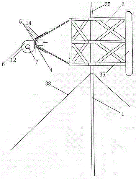
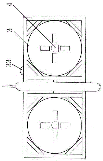
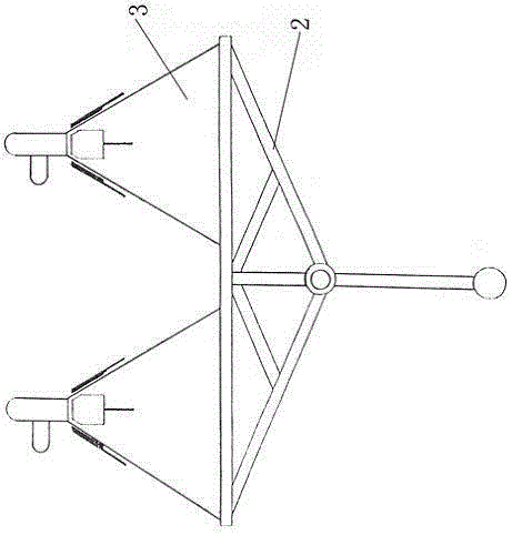
[0049] Embodiment 1: The direct impact type wind power generation equipment unit adopting the wind collector of this example, such as figure 1 , figure 2 , image 3 , including a tower tube 1, a diagonal stay rod 38 is connected to the tower tube, a tower frame 2 is fixed on the tower tube, a lightning rod 35 is provided on the tower frame, and a counterweight 36 is provided at the front end of the tower frame. The rear portion of the tower is fixed with a double-connected horn-shaped wind collector 3, and the plane of the opening of the horn-shaped wind collector is circular. The tower frame is located directly in front of the gap between the two horn-shaped air collectors. An air outlet 4 is provided in the middle of the rear of the horn-shaped air collector, and an air outlet 5 is provided around the air outlet. The air outlets are up, down, left, and right. 4 evenly distributed, the rear end of the trumpet-shaped air collector is connected with the wind impeller box 6 a...

Embodiment 2

[0053] Embodiment 2: The direct impact type wind power generation equipment unit adopting the wind collector of this example, such as figure 1 , figure 2 , image 3 , The plane of the opening of the trumpet-type air collector 3 is a square, and the rest are the same as in Embodiment 1.

Embodiment 3

[0054] Embodiment 3: The direct-impact wind power generation equipment unit using the wind collector in this example is a low-level horizontal axis unit, such as Figure 10 , the wind impeller box 6 is connected with the wind impeller box frame 17, the lower end of the wind impeller box frame is provided with a revolving wheel 18, the revolving wheel is connected on the revolving track 19 of the wind turbine, and the wind impeller box frame and the tower frame 2 are fixed There is wind impeller box support file 20.

[0055] All the other are with embodiment 1.


PUM


Abstract

The invention relates to a wind power generation equipment unit in the new energy industry, in particular to a straight hit type wind power generation equipment unit adopting air collecting machines. The straight hit type wind power generation equipment unit is adopted mainly for solving the technical problems, existing in the prior art, such as the too high power generation cost caused by the too low wind power utilization efficiency and power generation efficiency of wind power generation equipment. The straight hit type wind power generation equipment unit comprises a tower frame (2). The dual-connecting type trumpet-shaped air collecting machines (3) are fixed to the rear portion of the tower frame (2). The tower frame is located in right front of the gap between the two trumpet-shaped air collecting machines. The center of the rear portion of each trumpet-shaped air collecting machine is provided with a wind outlet (4). Wind discharging outlets (5) are arranged on the periphery of the wind outlets. The rear ends of the trumpet-shaped air collecting machines are connected with wind impeller boxes (6) and machine rooms (7). The rear portions of the wind impeller boxes are provided with wind exhausting outlets.

Description

technical field [0001] The invention relates to a wind power generator set in the new energy industry, in particular to a direct-impact wind power generator set using a wind collector. Background technique [0002] Wind energy is a non-polluting renewable energy source. It is inexhaustible, inexhaustible, and widely distributed, wind energy can be freely obtained in unlimited quantities. But in reality, when wind power is used to generate wind power, its power generation cost is higher than that of chemical energy such as petroleum and coal. [0003] At present, the vast majority of wind power generation equipment widely used in the society adopts horizontal axis propeller lift type power generation equipment, but in actual use, the wind power utilization efficiency and power generation efficiency of wind power generation equipment are too low, resulting in high power generation costs. Although wind power is non-polluting and very environmentally friendly compared with the...

Claims


Application Information

Patent Timeline
Patent Type & Authority Applications(China)
IPC IPC(8): F03D1/04F03D3/04F03D9/00
CPCY02E10/72Y02E10/74
Inventor 王正清陈芳芳
Owner 王正清
Why Eureka
Try Eureka