
Rotary continuous feeding device

A technology of feeding device and rotating shaft, applied in the combustion method, combustion type, incinerator, etc., can solve the problems of low efficiency and safety of incinerators, and achieve continuous and equivalent high-efficiency incineration, high safety performance, and low labor intensity. Effect

Active Publication Date: 2015-11-25
池州中宏运环保设备有限公司
View PDF6 Cites 0 Cited by
  • Summary
  • Abstract
  • Description
  • Claims
  • Application Information

AI Technical Summary

Problems solved by technology

[0003] The technical problem to be solved by the present invention is to provide a rotary continuous feeding device to solve the problem of low efficiency and safety when throwing incinerated objects

Method used


Image

  • Rotary continuous feeding device
  • Rotary continuous feeding device
  • Rotary continuous feeding device

Examples


Embodiment Construction

[0023] In the following, numerous specific details are set forth in order to provide a thorough understanding of the concepts underlying the described embodiments. It will be apparent, however, to one skilled in the art that the described embodiments may be practiced without some or all of these specific details. In other instances, well known processing steps have not been described in detail.

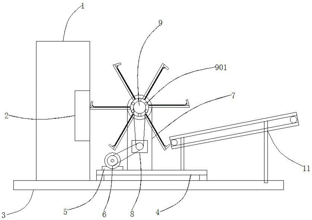
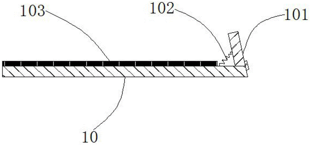
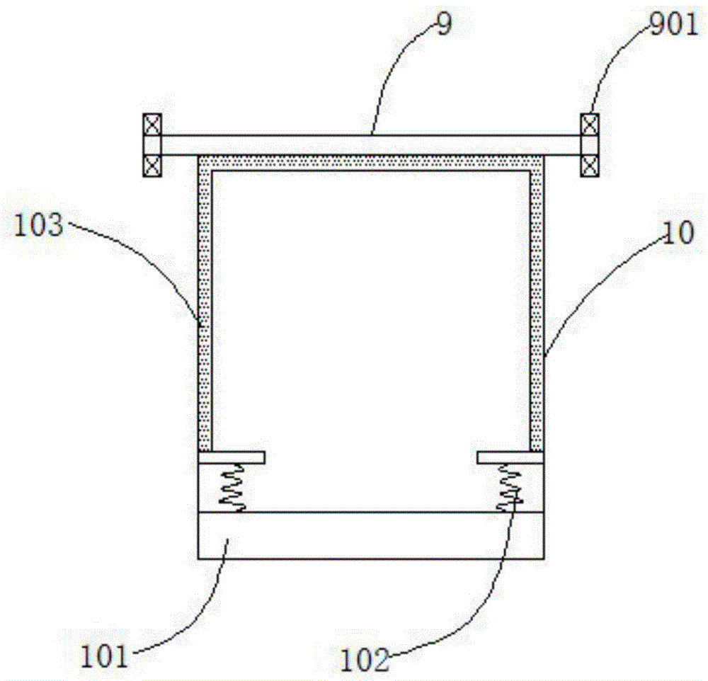
[0024] Such as figure 1 , figure 2 , image 3 As shown, it includes a furnace body 1, a feeding port 2, a working platform 3, a frame 4, a motor 5, a transmission wheel 6, a support frame 7, a reducer 8, a rotating shaft 9, a partition 10, a conveyor 11, a bearing 901, Turn plate 101, spring 102, sealing strip 103, frame 4 is positioned at the top of working platform 3, and motor 5 is positioned at the right side of frame 4 top, and the two are screwed together, and drive wheel 6 runs through motor rotating shaft 9, and the two are connected in rotation, The support frame 7 is lo...


PUM


Abstract

The invention discloses a rotary continuous feeding device. The rotary continuous feeding device comprises a furnace stack, a feeding opening and a working platform, and is characterized by comprising a rack, a motor, a driving wheel, a support frame, a reducer, a rotating shaft, partitions and a conveyor, wherein the rack is located at the top of the working platform; the motor is located on the right side of the top of the rack, and the motor and the rack are in threaded connection; the driving wheel penetrates the rotating shaft of the motor, and the driving wheel and the rotating shaft of the motor are in rotational connection; the support frame is located in the center of the top of the rack, and the support frame and the rack are in threaded connection; the reducer is located on the right side of the support frame, and the reducer and the support frame are in threaded connection; the rotating shaft is located in the center of the support frame, and the rotating shaft and the support frame are in rotational connection; the partitions are located on the side wall of the rotating shaft and are a plurality of rectangular iron plates, and the partitions and the rotating shaft are in welded connection; and the conveyor is located on the front side of the top of the working platform, and the conveyor and the working platform are in threaded connection.

Description

technical field [0001] The invention relates to a feeding device, in particular to a rotary continuous feeding device. Background technique [0002] When throwing incinerators in traditional incinerators, the furnace door is usually thrown directly. Because the volume of the incinerator is limited, it is necessary to continuously throw incineration materials while burning. Go out, produce the hidden danger of fire and burn throwing personnel, in view of above-mentioned defective, be necessary to design a kind of rotating continuous feeding device. Contents of the invention [0003] The technical problem to be solved by the present invention is to provide a rotary continuous feeding device to solve the problem of low efficiency and safety when throwing incinerated objects. [0004] In order to solve the above technical problems, the technical solution of the present invention is: a rotary continuous feeding device, including a furnace body, a feeding port, a working platfo...

Claims


Application Information

Patent Timeline
Patent Type & Authority Applications(China)
IPC IPC(8): F23G5/44
Inventor 洪国元汪建华
Owner 池州中宏运环保设备有限公司
Learn More