Engine oil inflation device for engine oil pump testing device

A technology of a testing device and an inflating device, which is applied in the field of machine testing, can solve problems such as uneven gas content, increased output pressure, and uneven distribution, and achieve the effects of uniform gas content in engine oil, slow mixing speed, and uniform mixing

Active Publication Date: 2015-11-25
NINGBO SHENGLONG AUTOMOTIVE POWERTRAIN SYSTEM CO LTD
View PDF10 Cites 1 Cited by
  • Summary
  • Abstract
  • Description
  • Claims
  • Application Information

AI Technical Summary

Problems solved by technology

[0005] 1) For the former, after the air pump transports the gas into the oil tank through the air pipe, the gas is dissolved in the oil, but the distribution of the gas in the oil is uneven, and the gas content at the connection between the air pipe and the oil tank will be high, while The farther away from the connection, the lower the gas content. Therefore, the gas content in the oil supplied from the oil tank to the oil pump is not uniform, and the output pressure of the oil pump increases with the reduction of the gas content. In this way, the oil pump does not If the pressure cannot be output stably and reflected on the engine, it cannot truly reflect the operating conditions of the engine;
[0006] 2) As for the latter, it is purely a difference between the volume change of the hot oil and the oil at normal temperature, and the gas content in the engine oil is calculated by a certain calculation method. Therefore, its detection The efficiency is too low and the error is large

Method used


Image

  • Engine oil inflation device for engine oil pump testing device
  • Engine oil inflation device for engine oil pump testing device
  • Engine oil inflation device for engine oil pump testing device

Examples


Embodiment Construction

[0025] The present invention will be described in further detail below in conjunction with the accompanying drawings and specific embodiments.

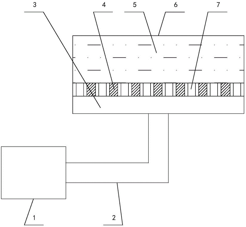
[0026] Depend on figure 1 and figure 2 As can be seen from the structural schematic diagram of the oil charging device of the present invention used in the oil pump testing device, it includes an air pump 1, an oil tank 6 for supplying oil to the oil pump inlet and a gas pipe 2 communicating with the air pump 1 and the oil tank 6. It also includes a partition 4, the partition 4 is provided with a plurality of through holes 7 covering the entire partition 4, the edge of the partition 4 is connected to the inner side wall of the fuel tank 6, and is located near the inlet of the air pipe 2. port.

[0027] The connection port between the air pipe 2 and the fuel tank 6 is located at the bottom of the fuel tank 6 , and the partition plate 4 and the bottom of the fuel tank 6 have a chamber, which is the gas storage chamber 3 .

[0028] T...


PUM


Abstract

The invention discloses an engine oil inflation device for an engine oil pump testing device. The engine oil inflation device comprises an air pump (1), an oil tank (6) for supplying oil to an oil inlet of an engine oil pump and an air pipe (2) for communicating the air pump (1) with the oil tank (6), and further comprises a division plate (4), wherein the division plate (4) is provided with a plurality of through holes (7) distributed in the whole division plate (4), and the edge of the division plate (4) is connected to the inner side wall of the oil tank (6) and approaches an introduction port of the air pipe (2). By adopting the engine oil inflation device, the gas content of oil is uniform, and the situations that the gas content at the joint of the air pipe and the oil tank is high and the gas content away from the joint is lower are avoided, so that the engine oil pump can output pressure more stably and the using condition of an engine can be reflected more truthfully.

Description

technical field [0001] The invention relates to the technical field of engine testing, in particular to an engine oil aerating device used in an engine oil pump testing device. Background technique [0002] When the automobile engine is working, each moving part acts on another part with a certain force, and high-speed relative motion occurs. With relative motion, friction will inevitably occur on the surface of the parts, thereby accelerating wear. Therefore, in order to reduce wear and tear, reduce friction resistance and prolong service life, there must be lubrication system parts on the engine. The main components of the lubrication system are various equipment such as an oil pump. The function of the oil pump is to increase the oil to a certain pressure and then forcefully send it to the moving surfaces of the various parts of the engine. [0003] In the actual use of the engine, the engine oil has a certain gas content, because a small amount of gas will enter the oil...

Claims


Application Information

Patent Timeline
Patent Type & Authority Applications(China)
IPC IPC(8): G01M15/02B01F5/06B01F3/04
Inventor 李阳星罗玉龙周培良项鑫胡灵勇廖小华
Owner NINGBO SHENGLONG AUTOMOTIVE POWERTRAIN SYSTEM CO LTD
Why Eureka
Try Eureka