Display panel and making method and display device thereof

A display panel and display area technology, applied in the direction of nonlinear optics, instruments, optics, etc., can solve the problems of easy oxidation, flickering, corrosion and even falling off, and achieve the effect of eliminating the accumulation of static electricity

Active Publication Date: 2015-11-25
BOE TECH GRP CO LTD
View PDF5 Cites 26 Cited by
  • Summary
  • Abstract
  • Description
  • Claims
  • Application Information

AI Technical Summary

Problems solved by technology

[0005] However, this silver-coated glue conduction method has the following defects: First, due to the nature of the silver glue itself, it is very easy to oxidize, corrode, and even fall off, which leads to the disconnection between the transparent conductive layer on the back of the color filter substrate and the array substrate. The virtual connection or even disconnection between the wires will cause the static electricity on the back of the color film substrate to be eliminated, and obvious defects such as flickering will occur, which will affect the display effect and product yield. Secondly, due to the strong fluidity of the silver glue, it is easy to penetrate into the color film The film substrate and the array substrate are connected to other parts, resulting in defects, such as: silver glue penetrates between the color filter substrate and the array substrate, causing the black matrix to connect the transparent conductive layer on the back of the color filter substrate and the grounding wiring of the array substrate , so that the induced potential of the black matrix is ​​unbalanced, causing the periphery of the pixel to shine, and the macroscopic manifestation is the bad greenness of the screen.
[0006] To sum up, when the existing technology eliminates static electricity on the display panel, flickering, greenish screen and other defects will occur, which will affect the display effect and product yield.

Method used


Image

  • Display panel and making method and display device thereof
  • Display panel and making method and display device thereof
  • Display panel and making method and display device thereof

Examples


Embodiment 1

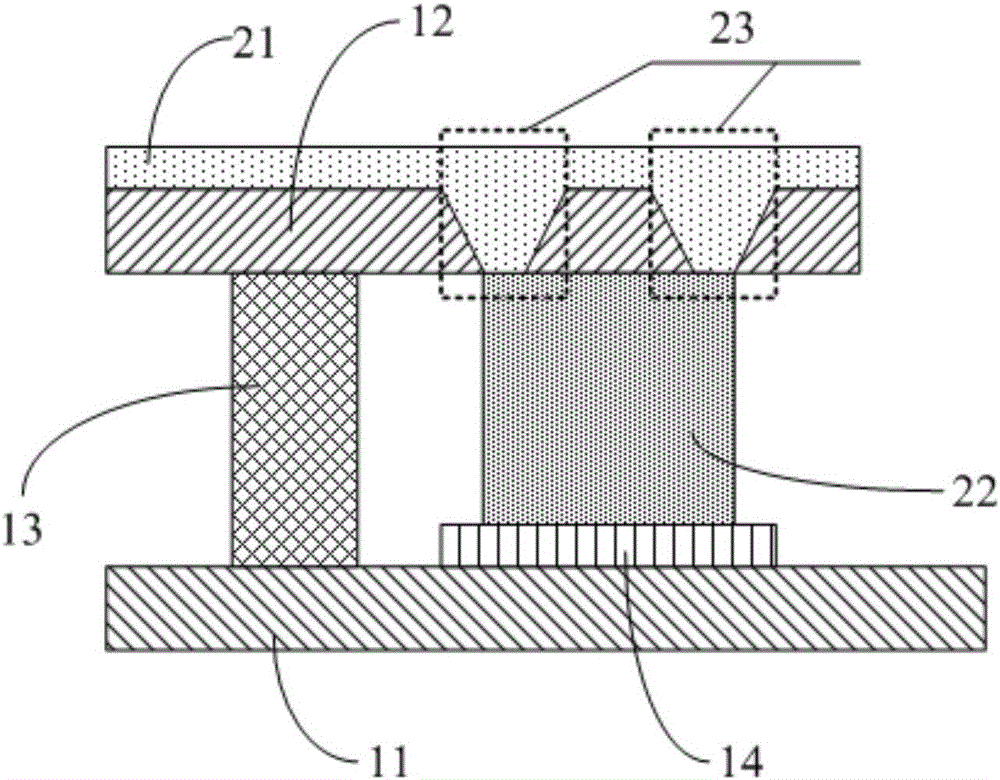
[0053] Such as Figure 4 As shown, the color filter substrate 12 in the specific embodiment of the present invention further includes a metal 40 disposed in the connection hole, and the transparent conductive layer 21 is connected to the conductive glue 22 through the metal 40 disposed in the connection hole. In the specific embodiment of the present invention, the material of the metal 40 may be aluminum (Al), molybdenum (Mo), etc., and the specific embodiment of the present invention does not specifically limit the material of the metal 40 .

[0054] Due to the small resistance of the metal 40, when the transparent conductive layer 21 is connected to the conductive glue 22 through the metal 40, the connection resistance will be reduced, so that the transparent conductive layer 21 can be better connected with the grounding wire 14 on the array substrate 11, thereby It can better eliminate the static electricity accumulation on the color filter substrate.

Embodiment 2

[0056] Such as Figure 5 As shown, the color filter substrate 12 in the specific embodiment of the present invention also includes a metal 40 arranged in the connection hole, and a metal wire 50 connected to the metal 40 and arranged on the side of the color filter substrate 12 facing away from the array substrate 11, transparent The conductive layer 21 is connected to the conductive glue 22 through the metal wire 50 and the metal 40 disposed in the connection hole, wherein the orthographic projection of the metal wire 50 on the array substrate 11 is located in the peripheral lead area of ​​the array substrate. The material of the metal wire 50 in the specific embodiment of the present invention can be aluminum (Al), molybdenum (Mo), etc. The specific embodiment of the present invention does not specifically limit the material of the metal wire. 40 and metal wire 50 are made of the same material.

[0057] Embodiment 2 of the present invention Compared with Embodiment 1, the m...

Embodiment 3

[0060] Such as Figure 6 As shown, the color filter substrate 12 in the specific embodiment of the present invention also includes a metal 40 arranged in the connection hole, and a metal wire 60 connected to the metal 40 and arranged on the side of the color filter substrate 12 facing the array substrate 11, which is transparent and conductive The layer 21 is connected to the conductive glue 22 through the metal wire 60 and the metal 40 disposed in the connection hole, wherein the orthographic projection of the metal wire 60 on the array substrate 11 is located in the peripheral lead area of ​​the array substrate. The material of the metal wire 60 in the specific embodiment of the present invention can be aluminum (Al), molybdenum (Mo), etc., the specific embodiment of the present invention does not specifically limit the material of the metal wire, during specific implementation, in the specific embodiment of the present invention The material of the metal wire 60 is the same...


PUM


Abstract

The invention discloses a display panel and a making method and display device thereof. The problems that in the prior art, flicker, green images and the like occur when static electricity is eliminated are avoided, and the display effect and the product yield are improved. The display panel comprises an array substrate and a color film substrate which are arranged oppositely, the array substrate comprises a display area and a peripheral lead area, and the peripheral lead area comprises a grounding line; the color film substrate comprises a transparent conducting layer dorsad facing the side of the array substrate, the display panel further comprises a conductive adhesive arranged between the array substrate and the color film substrate, the orthographic projection of the conductive adhesive on the array substrate is located in the peripheral lead area, and the conductive adhesive is connected with the grounding line; the color film substrate further comprises one ore more connection holes which penetrate through the color film substrate and are formed in an area corresponding to the peripheral lead area of the array substrate, and the transparent conductive layer is connected with the conductive adhesive through the connection holes.

Description

technical field [0001] The present invention relates to the field of display technology, in particular to a display panel, a manufacturing method thereof, and a display device. Background technique [0002] Thin Film Transistor Liquid Crystal Display (TFT-LCD) is a commonly used flat-panel display at present. Liquid crystal display panels are widely used in modern digital information equipment due to their small size, low power consumption, no radiation, and high resolution. . [0003] In the production process of TFT-LCD, due to the reasons of equipment and personnel, static electricity cannot be completely avoided. Generally speaking, a layer of transparent conductive layer is sputtered on the back of the color filter substrate to eliminate static electricity. The role of static electricity. But so far, how to introduce the static electricity on the ITO conductive layer to the grounding end, each manufacturer adopts different methods. At present, the most common way is ...

Claims


Application Information

Patent Timeline
Patent Type & Authority Applications(China)
IPC IPC(8): G02F1/1333G02F1/1362
CPCG02F1/1333G02F1/136204G02F1/136227
Inventor 刘广辉
Owner BOE TECH GRP CO LTD
Why Eureka
Try Eureka