Buffer-type terminal block

A junction box and buffer spring technology, applied in the direction of electrical components, etc., can solve the problems of easy damage to cables and junction boxes, unreasonable overall design, short service life, etc., to prevent cable detachment, simple structure, and prevent movement Effect

Active Publication Date: 2015-11-25
浙江中兴电缆有限公司
View PDF5 Cites 12 Cited by
  • Summary
  • Abstract
  • Description
  • Claims
  • Application Information

AI Technical Summary

Problems solved by technology

[0004] Although the above-mentioned solution solves the deficiencies of the prior art to a certain extent, the junction box does not have a buffer structure capable of buffering the external force, and the cables and the junction box are easily damaged under the action of strong force, and the service life is short. The design is not reasonable enough and the practicability is poor

Method used


Image

  • Buffer-type terminal block
  • Buffer-type terminal block

Examples


Embodiment

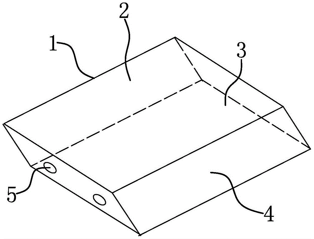
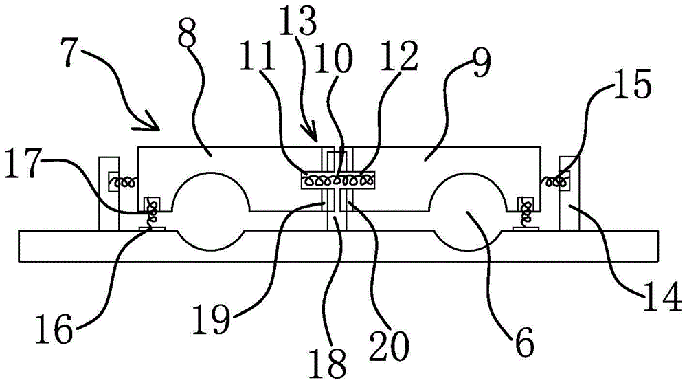
[0016] Such as Figure 1-2 As shown, the buffer type junction box includes a box body 1, a box cover 2 is provided on the box body 1, the box body 1 includes a bottom plate 3 and a surrounding edge 4, and the surrounding edge 4 is provided with a mounting hole 5 for cable insertion, and the bottom plate 3 is provided with two semi-cylindrical grooves 6 adapted to the cables, and the semi-cylindrical grooves 6 are provided with cable pressing blocks 7 capable of pressing the cables. The cable pressing blocks 7 include symmetrically arranged The first pressure divider block 8 and the second pressure divider block 9, between the first pressure divider block 8 and the second pressure divider block 9, there are two pressure divider blocks 8 and the second pressure divider block 9 which have direction to the first pressure divider block 8 and the second pressure divider block 9 The first buffer spring 10 of the external pre-tightening force, the first mounting groove 11 for the inst...


PUM


Abstract

The invention belongs to the technical field of electric equipment, and particularly relates to a buffer-type terminal block. The buffer-type terminal block comprises a box body, wherein a box cover is arranged on the box body; the box body comprises a bottom plate and a surrounding edge; a mounting hole is formed in the surrounding edge; two semi-cylindrical grooves are formed in the bottom plate; a cable pressure block is arranged on each semi-cylindrical groove, and comprises a first partial pressure block and a second partial pressure block; two first buffer springs are arranged between the first partial pressure block and the second partial pressure block; a first mounting groove is formed in the first partial pressure block; a second mounting groove is formed in the second partial pressure block; clamping blocks are arranged at the outer end part of the first partial pressure block and the outer end part of the second partial pressure block; second buffer springs are respectively arranged between the clamping blocks and the first partial pressure block and the second partial pressure block; a support plate is arranged on the bottom plate; a third buffer spring is arranged between the support plate and the cable pressure block; and a guide post is arranged on the bottom plate. The buffer-type terminal block has the advantages that the buffer-type terminal block is reasonable in design, and has a buffer effect on external strong force.

Description

technical field [0001] The invention belongs to the technical field of electrical equipment, in particular to a buffer junction box. Background technique [0002] The junction box is one of the electrical accessories, because the wires used for decoration pass through the wire tube, and the junction box is used as a transition at the joint of the wire. It plays the role of protecting the wires and connecting wires, but the cables and junction boxes in the prior art are prone to damage under the action of strong force, and the control box does not have a junction box that can buffer the external force , the service life is short, the overall design is not reasonable enough, and the practicability is poor. [0003] In order to improve the existing technology, people have carried out long-term exploration and proposed various solutions. For example, the Chinese patent literature discloses a photovoltaic junction box [application number: CN201220716629.2], which includes a box...

Claims


Application Information

Patent Timeline
Patent Type & Authority Applications(China)
IPC IPC(8): H02G3/08
Inventor 潘通滨
Owner 浙江中兴电缆有限公司
Why Eureka
Try Eureka