
Converter and voltage clamping circuit therein

一种电压箝位、变换器的技术,应用在变换器领域,能够解决变换器无法正常工作、开关损坏等问题,达到元件减少、可靠度增加、制作成本减少的效果

Active Publication Date: 2015-11-25
DELTA ELECTRONICS (SHANGHAI) CO LTD
View PDF8 Cites 6 Cited by
  • Summary
  • Abstract
  • Description
  • Claims
  • Application Information

AI Technical Summary

Problems solved by technology

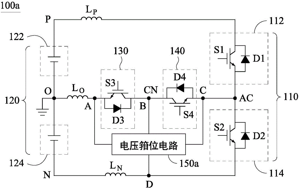
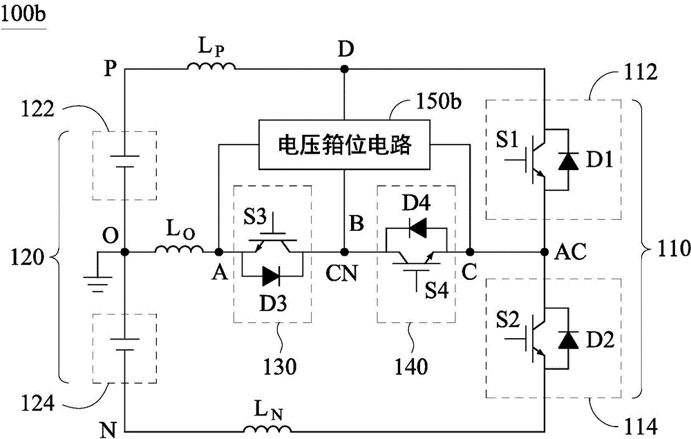
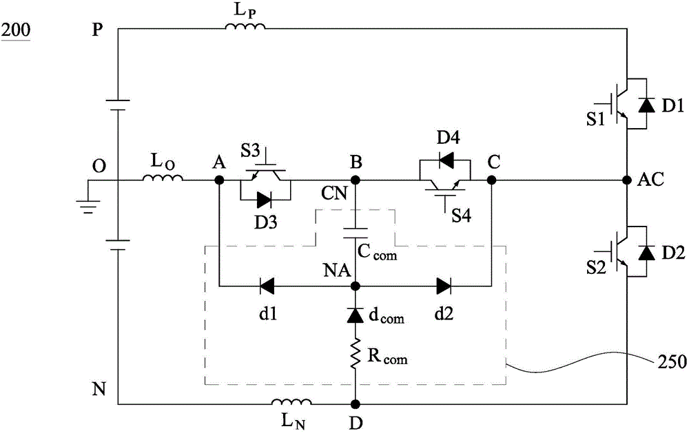
[0005] The content of the present invention is about a converter and the voltage clamping circuit in it, so as to solve the problem that the switch is damaged due to voltage surge, and then the converter cannot work normally

Method used


Image

  • Converter and voltage clamping circuit therein
  • Converter and voltage clamping circuit therein
  • Converter and voltage clamping circuit therein

Examples


Embodiment Construction

[0052] The following is a detailed description of embodiments with accompanying drawings, but the provided embodiments are not used to limit the scope of the present invention, and the description of the structure operation is not used to limit the order of its execution, any recombination of components The structure of, and the devices with equal effects are all within the scope of the present invention. In addition, the drawings are for illustrative purposes only, and are not drawn according to the original dimensions. For ease of understanding, the same elements in the following description will be described with the same symbols.

[0053] Unless otherwise specified, the terms used in the entire specification and claims usually have the usual meaning of each term used in this field, in the content disclosed here, and in the special content. Some terms used to describe the present disclosure will be discussed below or elsewhere in this specification to provide those skilled in...


PUM


Abstract

A converter includes a first bridge arm, a second bridge arm, two switch units and a voltage clamp circuit. The first bridge arm includes a first switch unit and a second switch unit that are electrically coupled in series at an output terminal. The second bridge arm includes two voltage sources that are electrically coupled in series at a neutral point terminal. The two switch units are electrically coupled in series at a common connection terminal, and are arranged between the neutral point terminal and the output terminal. The voltage clamp circuit is electrically coupled to the output terminal, the common connection terminal, the neutral point terminal, and one of a positive input terminal or a negative input terminal, and the circuit is shared by the two switch units to clamp voltages across the two switch units.

Description

Technical field [0001] The content of the present invention relates to a converter, and more particularly to a voltage clamping circuit in the converter. Background technique [0002] Generally speaking, converters with multi-level outputs are widely used in related fields, such as: solar inverters (solarinverter), uninterrupted power supply systems (UPS), power conditioning systems (PCS), etc. [0003] The above-mentioned converter usually includes elements such as switches, and the switches located on the current commutation path are switched to perform current commutation operations. [0004] However, parasitic inductance usually exists in the current path. Therefore, during the transient period when the aforementioned switch is switched, the presence of the parasitic inductance will cause the aforementioned switch to withstand a higher voltage, and even when the aforementioned switch is turned off, a voltage spike will be generated. ) Affect the aforementioned switches. For exa...

Claims


Application Information

Patent Timeline
Patent Type & Authority Applications(China)
IPC IPC(8): H02M7/487H02M7/5387H02M1/00
CPCH02M1/32H02M1/34H02M3/04H02M7/487H02M2001/346Y02B70/10H02M1/346H02M7/217H02M7/5387H02M7/219H02M1/342H02M1/344H02M1/348
Inventor 冯维一张伟强吴洪洋
Owner DELTA ELECTRONICS (SHANGHAI) CO LTD
Learn More