
Camera module and electronic equipment

A camera module and terminal technology, applied in TV, electrical components, color TV, etc., can solve the problems of inconvenient, non-uniform interface, large camera module, etc., and achieve the effect of reducing volume and facilitating installation and testing

Inactive Publication Date: 2015-11-25
NANCHANG O FILM OPTICAL ELECTRONICS TECH CO LTD +3
View PDF3 Cites 7 Cited by
  • Summary
  • Abstract
  • Description
  • Claims
  • Application Information

AI Technical Summary

Problems solved by technology

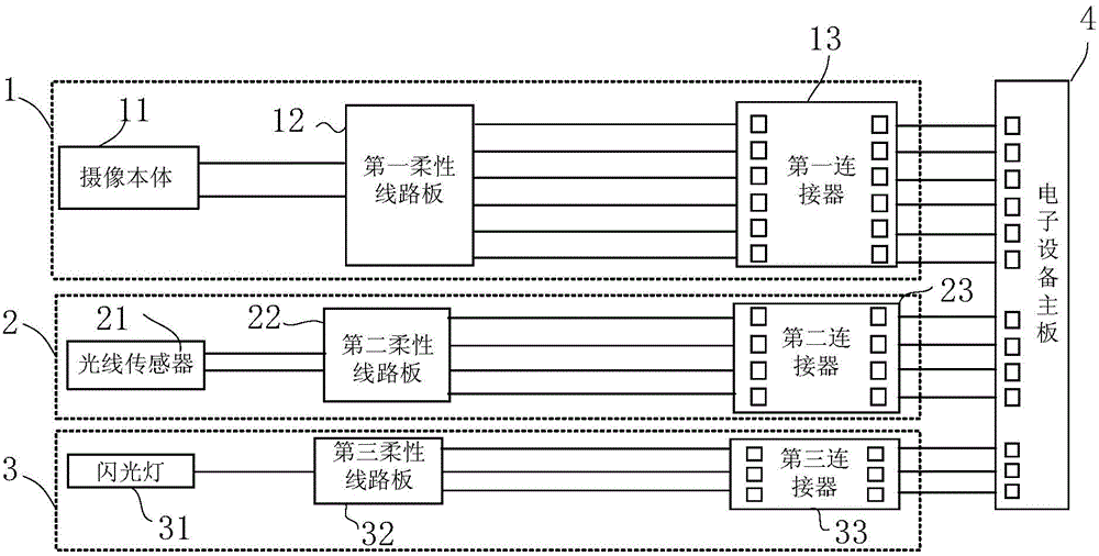
[0004] When a camera module is installed on an electronic device, three interfaces need to be connected between the camera module and the electronic device main board 4, which is time-consuming and laborious, and the camera module has a large volume; in addition, when the camera module is externally tested , because the first connector 13, the second connector 23 and the third connector 33 are used to connect the interface of the mainboard 4 of the electronic equipment is not uniform, so it is necessary to prepare the first connector 13, the second connector 23 and the third connector corresponding to the above. Connector 33 is a connector with a combination of three interfaces, which is very inconvenient

Method used


Image

  • Camera module and electronic equipment
  • Camera module and electronic equipment
  • Camera module and electronic equipment

Examples


Embodiment 2

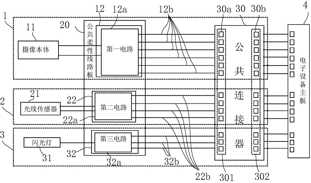
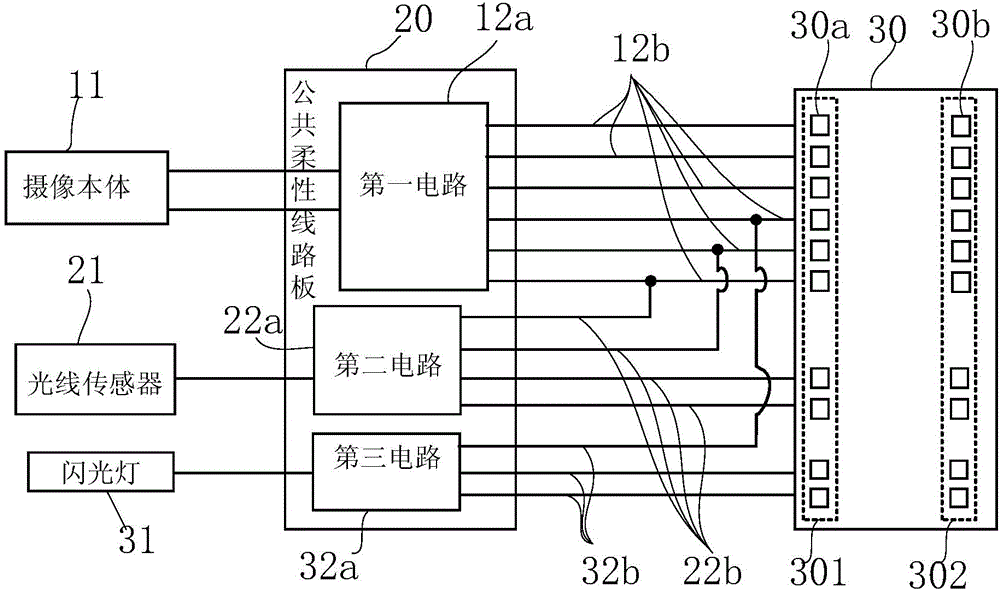
[0032] As a preferred implementation of the above-mentioned embodiment one: as figure 2 As shown, at least two of the first lead 12b, the second lead 22b and the third lead 32b are connected in parallel; the parallel first lead 12b and the second lead 22b, the first lead 12b and the third lead 32b, the second lead 22b and the third lead 32b, or the first lead 12b and the second lead 22b and the third lead 32b are all connected to the same terminal 30a integrated in the first interface.

[0033] In this scheme, the parallel connection forms of each lead wire include the following four types:

[0034] The first parallel connection form: the first lead wire 12b is connected in parallel with the second lead wire 22b;

[0035] The second parallel connection form: the first lead wire 12b is connected in parallel with the third lead wire 32b;

[0036] The third parallel connection form: the second lead wire 22b is connected in parallel with the third lead wire 32b;

[0037]The fo...


PUM


Abstract

The invention provides a camera module and electronic equipment. The camera module comprises a camera body module, a light sensor module and a flash lamp module, wherein the camera body module comprises a camera body, a first flexible circuit board and a first connector; the light sensor module comprises a light sensor, a second flexible circuit board and a second connector; the flash lamp module comprises a flash lamp, a third flexible circuit board and a third connector; the first flexible circuit board, the second flexible circuit board and the third flexible circuit board are integrated on a common flexible circuit board; terminals, which are connected with the flexible circuit boards, on the first connector, the second connector and the third connector are integrated in a first interface of a common connector; and terminals, which are connected with a mobile phone motherboard, on the first connector, the second connector and the third connector, are integrated in a second interface of the common connector. Installation can be completed once the second interface is connected with the motherboard of the electric equipment. No connector needs to be configured in test. Installation and test of the camera module are facilitated. Only one flexible circuit board and one connector are arranged, so that the size of the camera module is reduced.

Description

technical field [0001] The invention relates to electronic equipment imaging technology, in particular to an imaging module and electronic equipment. Background technique [0002] Existing mobile electronic devices such as mobile phones, electronic watches, tablet computers, and notebooks are usually equipped with camera modules. Especially with the emergence of smart phones and tablet computers and consumers' demand for continuous reduction in overall costs, these electronic devices are rapidly developing. , but it is also necessary to make electronic equipment develop towards the trend of lightness and thinness. [0003] Existing camera modules such as figure 1 As shown, it includes a camera body module 1, a light sensor module 2 and a flash module 3; the camera body module 1 includes a camera body 11, a first flexible circuit board 12 and a first connector 13; the light sensor module 2 includes a light sensor 21. The second flexible circuit board 22 and the second conne...

Claims


Application Information

Patent Timeline
IPC IPC(8): H04N5/225
Inventor 齐书刘燕妮
Owner NANCHANG O FILM OPTICAL ELECTRONICS TECH CO LTD
Learn More