Electric locomotive speed reducer assembly noise testing device and testing method thereof

A technology for testing devices and reducers, which is applied in the testing of machines/structural components, measuring devices, testing of mechanical components, etc. It can solve the problems of troublesome test installation, noise generation, troublesome operation, etc., and achieve the effect of convenient operation

Pending Publication Date: 2021-01-29
WUXI JINGHUA AUTO PARTS
View PDF0 Cites 2 Cited by
  • Summary
  • Abstract
  • Description
  • Claims
  • Application Information

AI Technical Summary

Problems solved by technology

[0002] The electric vehicle reducer is an important part for connecting the drive end motor and the drive half shaft. When the reducer is working, the gears in the reducer rub against each other, which will generate noise. Load and sliding noise, the traditional test needs to be tested on the car, the test installation is troublesome, and the operation is troublesome

Method used


Image

  • Electric locomotive speed reducer assembly noise testing device and testing method thereof
  • Electric locomotive speed reducer assembly noise testing device and testing method thereof
  • Electric locomotive speed reducer assembly noise testing device and testing method thereof

Examples


Embodiment Construction

[0026] The specific implementation of this embodiment will be described below in conjunction with the accompanying drawings.

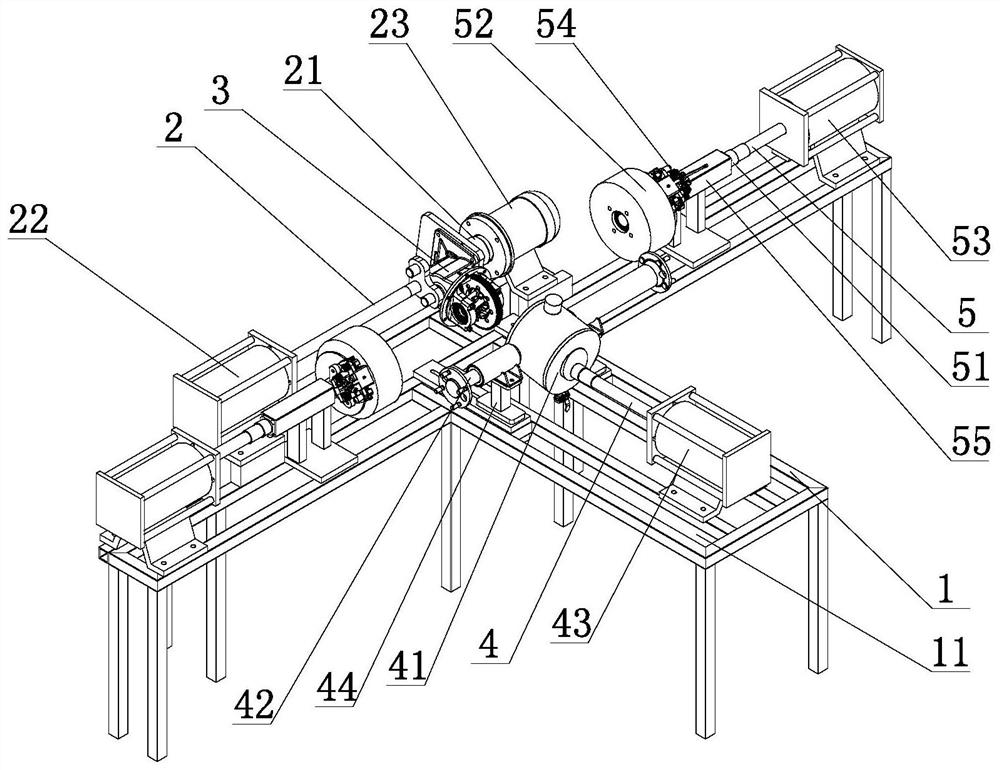
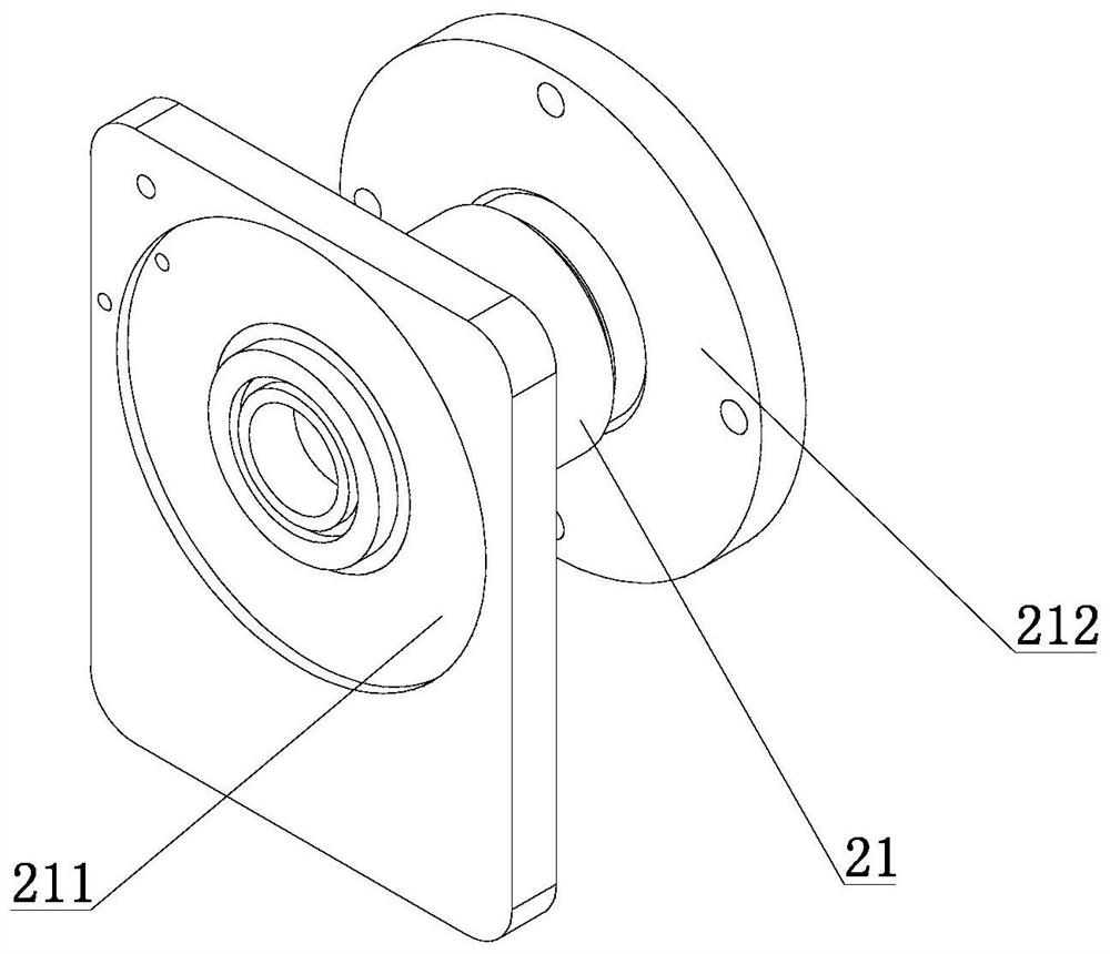
[0027] Such as Figure 1 to Figure 8 As shown, the noise test device of the electric locomotive reducer assembly in this embodiment includes a frame 1, on which the reducer connecting mechanism 2 is connected, the reducer connecting mechanism 2 includes a transmission mechanism 21, and the transmission mechanism 21 includes a rotating seat 211 , the rotating seat 211 is rotatably connected to the motor connection flange seat 212, the reducer assembly 3 is pressed on the rotating seat 211 by the first driving cylinder 22, and the mounting surface of the rotating seat 211 is respectively provided with three Different connecting holes can be fixedly connected to different reducer assemblies 3 on the mounting surface of the rotating base 211 through different connecting holes, the motor connection flange seat 212 is connected to the drive motor 23, and the...


PUM


Abstract

The invention relates to an electric locomotive speed reducer assembly noise testing device and a testing method thereof. The electric locomotive speed reducer assembly noise testing device comprisesa rack, a speed reducer connecting mechanism, a half-shaft axle housing connecting mechanism and a load mechanism are connected with the rack, and the speed reducer connecting mechanism comprises a transmission mechanism which comprises a rotating base and a motor connecting flange base; the speed reducer assembly is pressed on the rotating base through a first driving air cylinder, the motor connecting flange base is connected with a driving motor in driving connection with the speed reducer assembly, the half-shaft axle housing connecting mechanism comprises an axle housing body, an upper axle housing body connecting oil filling port, a lower axle housing body connecting oil filling port and an oil drain valve, two half shafts penetrate through the two sides of the axle housing body, andthe axle housing body is further connected with a second driving air cylinder. The load mechanism comprises a sliding shaft, the two ends of the sliding shaft are connected with a rotating shaft anda third driving air cylinder respectively, the rotating shaft is connected with a disc brake disc, and the sliding shaft matching the disc brake disc is connected with disc brake pincers. The electriclocomotive speed reducer assembly noise testing device and the testing method thereof are used for testing noise generated when the speed reducer assembly runs, and testing installation and operationare simple.

Description

technical field [0001] The invention relates to a noise test of a reducer assembly, in particular to a noise test device and a test method for an electric locomotive reducer assembly. Background technique [0002] The electric vehicle reducer is an important part for connecting the drive end motor and the drive half shaft. When the reducer is working, the gears in the reducer rub against each other, which will generate noise. The load and sliding noise, the traditional test needs to be tested on the car, the test installation is troublesome, and the operation is troublesome. Contents of the invention [0003] In view of the above shortcomings, the applicant has made researches and improvements, and provides a noise testing device and testing method for an electric locomotive reducer assembly. [0004] The technical scheme adopted in the present invention is as follows: [0005] A noise test device for an electric locomotive reducer assembly, comprising a frame on which a...

Claims


Application Information

Patent Timeline
Patent Type & Authority Applications(China)
IPC IPC(8): G01M13/028G01M13/025
CPCG01M13/025G01M13/028
Inventor 高福亮强晶张海斐
Owner WUXI JINGHUA AUTO PARTS
Why Eureka
Try Eureka