Lighting device and method for controlling the lighting device

A lighting device and control method technology, applied in the direction of lighting devices, energy-saving control technology, electric lamp circuit layout, etc., can solve problems such as difficult to distinguish, complex management of lighting appliances, etc.

Active Publication Date: 2019-01-11
PANASONIC INTELLECTUAL PROPERTY MANAGEMENT CO LTD
View PDF6 Cites 0 Cited by
  • Summary
  • Abstract
  • Description
  • Claims
  • Application Information

AI Technical Summary

Problems solved by technology

For this reason, for example, in a lighting system configuration in which a plurality of lighting fixtures installed in one room are operated by one panel unit, the management of each lighting fixture becomes complicated, and it may also be difficult to distinguish which lighting fixture is related to the notification content. Corresponding situation

Method used


Image

  • Lighting device and method for controlling the lighting device
  • Lighting device and method for controlling the lighting device
  • Lighting device and method for controlling the lighting device

Examples


Deformed example 1

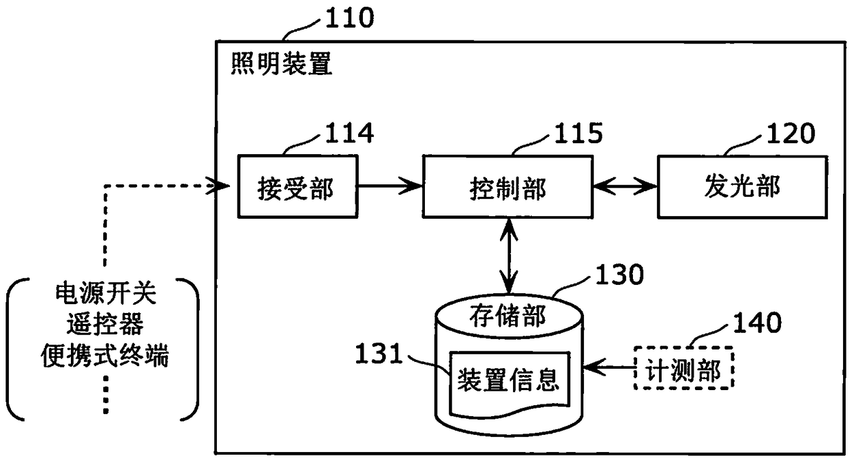
[0121] Figure 6 It is a block diagram showing the outline of the configuration of the lighting device 110 according to Modification 1 of the embodiment.

[0122] Figure 7 It is a flowchart showing the workflow of the lighting device 110 according to Modification 1 of the embodiment.

[0123] Figure 6 The lighting device 110 according to Modification 1 shown above is characterized in that a threshold value related to the accumulated lighting time of the light emitting unit 120 is applied to the color tone control in the information notification mode. Specifically, in the lighting device 110 according to Modification 1, color tone control is performed according to the comparison result of the accumulated lighting time and the threshold value.

[0124] For example, when the user operates a remote control etc., a predetermined instruction for shifting to the information reporting mode is transmitted to the lighting device 110 together with information including a threshold (...

Deformed example 2

[0146] Figure 8 It is a block diagram showing the outline of the configuration of the lighting device 110 according to Modification 2 of the embodiment.

[0147] Figure 9 It is a flowchart showing the workflow of the lighting device 110 according to Modification 2 of the embodiment.

[0148] Figure 8 The lighting device 110 according to Modification 2 shown above is characterized in that time information indicating a predetermined time length is applied to color tone control in the information notification mode. Specifically, in the lighting device 110 according to Modification 2, the color adjustment control is performed according to the result of the comparison of the lighting device 110 calculated using the length of the accumulated lighting time. The length of life expectancy compared to the length of time indicated by the time information.

[0149] For example, when the user operates a remote controller, a predetermined instruction for transitioning to the informat...

Deformed example 3

[0172] Figure 10 It is a block diagram showing the outline of the configuration of an illumination device 110 a according to Modification 3 of the embodiment.

[0173] Figure 11 It is a flowchart showing the workflow of the lighting device 110 a according to Modification 3 of the embodiment.

[0174] Figure 10 The illuminating device 110 a according to the illustrated modification 3 differs from the illuminating device 110 according to the embodiment in that it does not include the measuring unit 140 . Furthermore, the lighting device 110 a according to Modification 3 is characterized in that the storage unit 130 stores the device information 131 showing the validity period of the lighting device 110 a.

[0175] Specifically, in the lighting device 110 a according to Modification 3, when the receiving unit 114 receives a predetermined instruction, the control unit 115 controls the light emitting unit 120 so that the effective period indicated by the device information 13...


PUM


Abstract

The invention provides an illuminating device capable of high efficiently reporting various information related to the illuminating device. The illuminating device (110) comprises a control part (115) and an illuminating part (120) controlling a lamp according to the control part (115), and further comprises a storage part (130) storing device information (131) indicating static or dynamic attribute information of the illuminating device (110) and a receiving part (114) receiving regulated indications, wherein after the control part (115) receives the regulated indications via the receiving part (114), the illuminating part (120) is controlled and color temperature of light emitted by the illuminating part (120) becomes color temperature stored in the device information (131) of the storage part (130).

Description

technical field [0001] The present invention relates to a lighting device including a light emitting unit that lights up under the control of a control unit. Background technique [0002] Conventionally, in lighting fixtures installed on ceilings, etc., the lifetime of a product is determined in consideration of deterioration of a light source, etc., and thus a technique of notifying the expiration of the lifetime has been disclosed. [0003] For example, in the technology disclosed in Patent Document 1, a time management unit and a notification unit are provided on a panel mounted on a wall, and when the accumulated lighting time of a lighting fixture measured by the time management unit reaches a predetermined time, the notification unit To inform the life of lighting fixtures. [0004] (Prior art literature) [0005] (patent documents) [0006] Patent Document 1 Japanese Unexamined Patent Publication No. 2008-251441 [0007] According to the above-mentioned convention...

Claims


Application Information

Patent Timeline
Patent Type & Authority Patents(China)
IPC IPC(8): H05B37/02
CPCY02B20/40
Inventor 菅原洋信田卓哉竹下博则
Owner PANASONIC INTELLECTUAL PROPERTY MANAGEMENT CO LTD
Why Eureka
Try Eureka