Method and apparatus for depositing atomic layers on substrate

A technology of atomic layer and atomic layer deposition, applied in the direction of coating, metal material coating process, gaseous chemical plating, etc., can solve the problems of substrate exposure and high risk of damage

Active Publication Date: 2015-11-25
NEDERLANDSE ORG VOOR TOEGEPAST-NATUURWETENSCHAPPELIJK ONDERZOEK (TNO)
View PDF8 Cites 8 Cited by
  • Summary
  • Abstract
  • Description
  • Claims
  • Application Information

AI Technical Summary

Problems solved by technology

While this provides an important advantage, the additional proce

Method used


Image

  • Method and apparatus for depositing atomic layers on substrate
  • Method and apparatus for depositing atomic layers on substrate
  • Method and apparatus for depositing atomic layers on substrate

Examples


Embodiment Construction

[0069] Unless otherwise stated, similar symbols indicate similar components throughout the drawings.

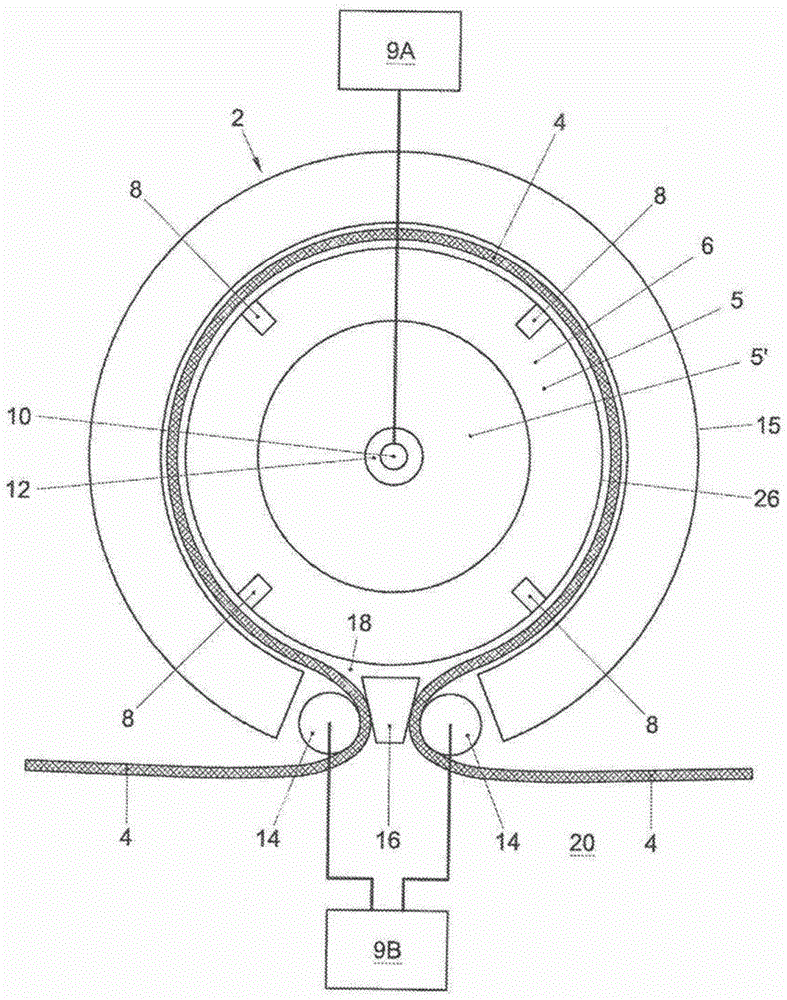
[0070] Atomic layer deposition is known as a method of depositing monolayer targets in at least two process steps, ie half cycles. The first of these self-limiting processing steps involves the application of precursor gases on the surface of the substrate. The second of these self-limiting processing steps involves reacting the precursor materials to form a monolayer target on the substrate. The precursor gas may, for example, include metal halide vapors such as hafnium tetrachloride (HfCl 4 ), but could equally include a precursor material such as a metalorganic vapor such as tetrakis-(ethyl-methyl-amino)hafnium or trimethylaluminum (Al(CH 3 ) 3 ). The precursor gas may be injected together with a carrier gas such as nitrogen, argon or hydrogen or mixtures thereof. The concentration of the precursor gas in the carrier gas can generally be in the range from 0.01 to 1% b...


PUM


Abstract

Method of performing atomic layer deposition. The method comprises supplying a precursor gas towards a substrate, using a deposition head including one or more gas supplies, including a precursor gas supply. The precursor gas reacts near a surface of the substrate for forming an atomic layer. The deposition head has an output face comprising the gas supplies, which at least partly faces the substrate surface during depositing the atomic layer. The output face has a substantially rounded shape defining a movement path of the substrate. The precursor-gas supply is moved relative to the substrate by rotating the deposition head while supplying the precursor gas, for depositing a stack of atomic layers while continuously moving in one direction. The surface of the substrate is kept contactless with the output face by means of a gas bearing.

Description

technical field [0001] The present invention relates to a method of performing atomic layer deposition on a substrate, the method comprising supplying a substrate with a precursor gas using a deposition head, the deposition head comprising one or more gas supplies, and the one or more gas supplies comprising A precursor gas supply for supplying a precursor gas; causing the precursor gas to approach, for example, react on a surface of a substrate to form an atomic layer, the deposition head having an output face at least partially facing the substrate surface when depositing the atomic layer , and the output face has one or more gas supplies and is substantially circular, the circle defining the movement path of the substrate, wherein the method further comprises rotating the deposition head relative to the substrate and along the The substrate moves the precursor gas supply, thereby depositing a stack of atomic layers while continuously moving the precursor gas supply in one d...

Claims


Application Information

Patent Timeline
IPC IPC(8): C23C16/455C23C16/458H01L21/314C23C16/54
CPCC23C16/45551C23C16/4409C23C16/45563C23C16/458C23C16/545C23C16/45544C23C16/46C23C16/481
Inventor 雷蒙德·雅各布斯·W·克纳彭R·奥利斯拉格斯丹尼斯·范登贝尔赫马泰斯·C·范登布尔弗雷迪·罗泽博姆
Owner NEDERLANDSE ORG VOOR TOEGEPAST-NATUURWETENSCHAPPELIJK ONDERZOEK (TNO)
Why Eureka
Try Eureka