
Automatic tracking and positioning fire water monitor and automatic tracking and positioning jet flow fire-extinguishing method
An automatic tracking and fire-fighting water cannon technology, which is applied in fire rescue and other directions, can solve problems such as the possibility that the flame has shifted to other positions, the deviation between the fire position and the positioning water spray position, and fire drift, etc., to achieve Fire tracking, fast and accurate positioning, and the effect of preventing missed inspections
- Summary
- Abstract
- Description
- Claims
- Application Information
AI Technical Summary
Problems solved by technology
Method used
Image

Examples
Embodiment Construction
[0037] The technical solutions of the present invention will be described in further detail below through specific implementation methods.
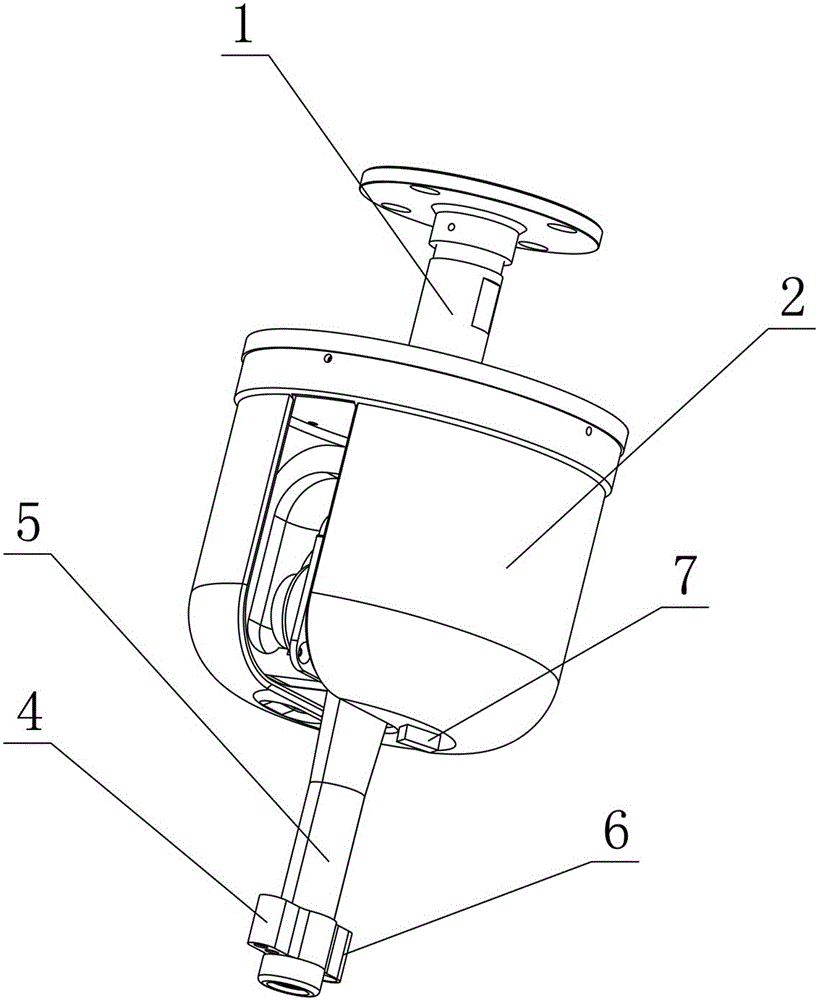
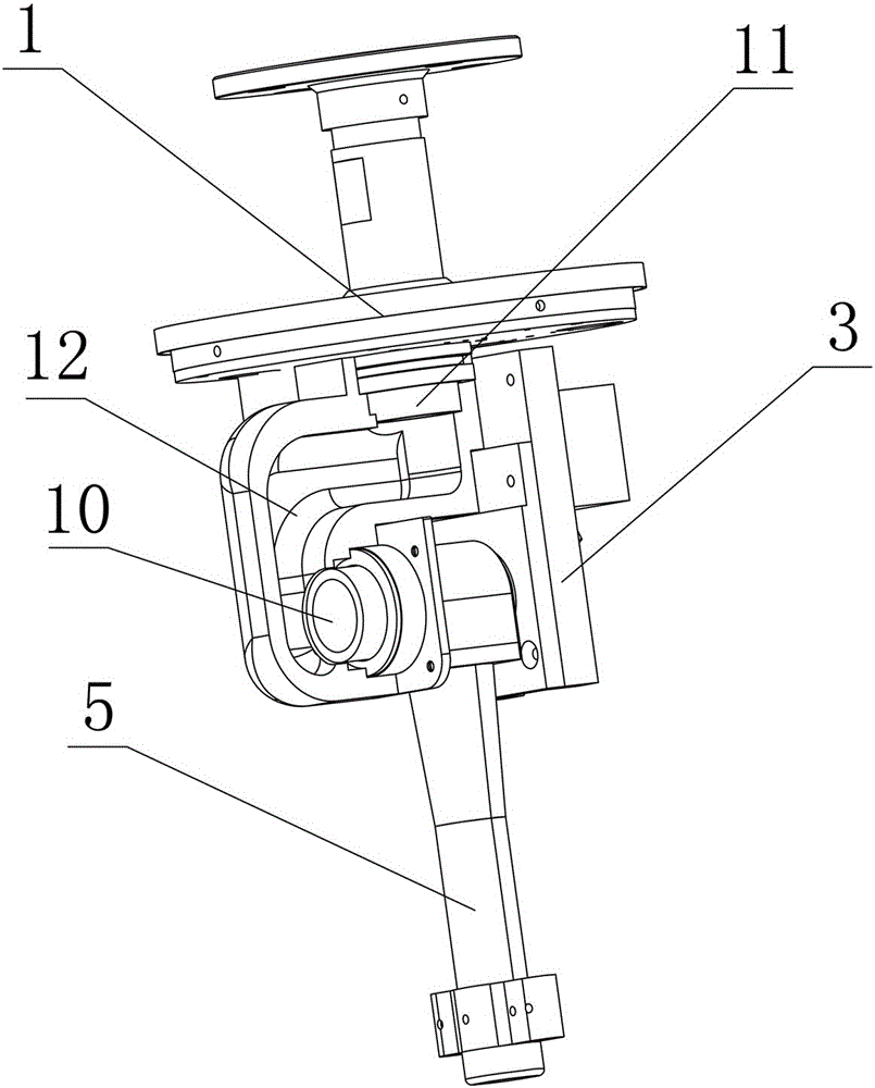
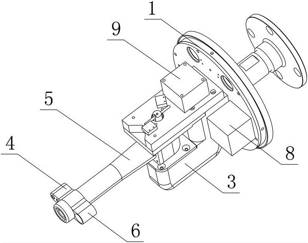
[0038] Such as Figure 1-Figure 3As shown, an automatic tracking and positioning fire-fighting water monitor 5 includes a base 1, a housing 2, a bracket 3 rotatably connected to the base 1, a water monitor 5 hinged on the bracket 3, and a water monitor mounted on the base 1. The infrared thermal imaging sensor 4 and the camera 6 on the 5, the processor connected to the infrared thermal imaging sensor 4 and the camera 6, and the electric control valve of the water pump connected to the processor, the remote control center, the display and the storage unit, the processor controls the level respectively The stepping motor 8 drives the support 3 to rotate horizontally, and controls the vertical stepping motor 9 to drive the water cannon 5 to rotate in the vertical plane. The processor is connected to a remote control center and a storage unit...
PUM
 Abstract
Description
Claims
Application Information