Supercharge Your Innovation With Domain-Expert AI Agents!

Wind guiding structure

A technology of air guide structure and air guide plate, which is applied in space heating and ventilation, space heating and ventilation details, and household heating, etc. Questions about the structure of the air outlet of the air guide grille, etc.

Active Publication Date: 2015-12-02
GREE ELECTRIC APPLIANCES INC
View PDF4 Cites 6 Cited by
  • Summary
  • Abstract
  • Description
  • Claims
  • Application Information

AI Technical Summary

Problems solved by technology

[0002] At present, the air outlet of the air-conditioning equipment on the market is usually equipped with an air deflector or grille to control the direction of the air outlet. The air guide baffle or grille is usually located at the air outlet and the position is very eye-catching. Detrimental to the overall aesthetics of air conditioning equipment
The prior art lacks an air outlet structure that can hide the air deflector or grille in the air outlet, so that users cannot directly observe the air deflector or grille from the outside

Method used


Image

  • Wind guiding structure
  • Wind guiding structure
  • Wind guiding structure

Examples


Embodiment 1

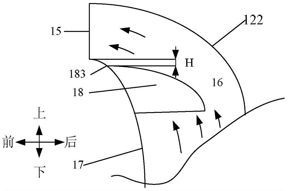
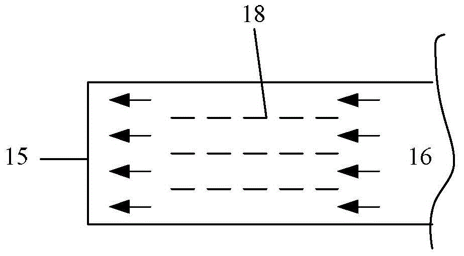
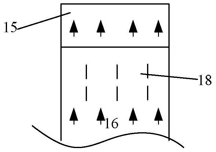
[0033] The first embodiment relates to an air guide structure, which includes an air supply channel, and the end of the air supply channel forms an air outlet. The air supply channel includes a first wall and a second wall disposed oppositely, and is located below the air outlet. A wind deflector is arranged between the first wall and the second wall, and the wind deflector extends in the front-rear direction. The height of the upper edge of the wind deflector is not higher than the height of the lower edge of the air outlet.

[0034] The air supply channel can be an air supply channel extending obliquely upward and forward; it can also be an air supply channel extending up and down (not shown in the figure). The air outlet is located at the upper end of the air supply channel and sends air toward the front. One wall is located on the front side, the second wall is located on the rear side, the wind deflector extends in the front-rear direction between the first wall and the secon...

Embodiment 2

[0036] Example two figure 2 -7 shows a specific application of the air guide structure of the present application on air conditioning equipment: where the top air supply channel 6 corresponds to the air supply channel 16 in the first embodiment, and the air deflector 22 corresponds to the air supply channel in the first embodiment. The second wall 122 and the decorative cover 7 correspond to the first wall 17 in the first embodiment, and the front side portion of the annular air outlet 61 between the diversion cover 22 and the decorative cover 7 corresponds to the air outlet 15 in the first embodiment.

[0037] in Figure 2-4 The air-conditioning equipment includes a cylindrical air-conditioning equipment housing 5, and the air-conditioning equipment housing 5 is provided with a main air duct and a wind generating device. The air-conditioning equipment air outlet structure in this embodiment includes a The top opening 9 is arranged obliquely with respect to the axial direction. S...


PUM


Abstract

The invention provides a wind guiding structure. The problems that a wind guiding structure arranged at a wind outlet, especially at a wind outlet which supplies air aslant upwards is exposed to the outside and the aesthetic perception of an appearance is influenced are mainly solved. The wind guiding structure comprises a wind feeding channel. A wind outlet is formed in the end portion of the wind feeding channel. The wind feeding channel comprises a first wall and a second wall, and the first wall and the second wall are arranged opposite to each other. A wind guiding plate is arranged on the lower portion of the wind outlet and between the first wall and the second wall. The wind guiding plate extends forwards and backwards. The height of the upper edge of the wind guiding plate is less than or equal to the height of the lower edge of the wind outlet. According to the wind guiding structure, the height of the wind guiding plate is arranged to be less than the height of the lower edge of the wind outlet, so the wind guiding plate can not be observed from the outside; the aesthetic perception of air conditioning equipment can be improved under the condition that the wind guiding function is not be influenced, so a customer can get a better experience.

Description

Technical field [0001] The present invention relates to the field of air conditioning equipment, and relates to electrical equipment used for conditioning indoor air, such as air conditioners, fans, and air purifiers. Specifically relates to a wind guide structure. Background technique [0002] At present, the air outlet of the air conditioning equipment on the market is usually equipped with a wind deflector or a wind deflector to control the direction of the wind. The wind deflector or wind deflector is usually located at the air outlet and the position is very eye-catching. It is detrimental to the overall aesthetics of the air conditioning equipment. In the prior art, there is a lack of an air outlet structure that can hide the air deflector or the air guide grid in the air outlet, so that the user cannot directly observe the air deflector or the air outlet structure from the outside. Summary of the invention [0003] In view of this, the present invention provides a wind gu...

Claims


Application Information

Patent Timeline
IPC IPC(8): F24F3/08
CPCF24F3/08F24F13/08F24F13/081
Inventor 李德清金海元孟宪运丘晓宏王朝新潘龙腾吴舸姚俊华张永成陈圣文臧允舒林裕亮曾庆和温骊杨杰
Owner GREE ELECTRIC APPLIANCES INC
Features
  • R&D
  • Intellectual Property
  • Life Sciences
  • Materials
  • Tech Scout
  • Unparalleled Data Quality
  • Higher Quality Content
  • 60% Fewer Hallucinations
Learn More