Apparatus and method of measuring eccentric throw of crankshaft

A technology of measuring device and eccentricity, applied in the direction of measuring device, mechanical measuring device, adopting mechanical device, etc., can solve problems such as waste, achieve the effect of saving production cost and solving difficult detection problems

Active Publication Date: 2015-12-02
CRRC QISHUYAN CO LTD
View PDF7 Cites 9 Cited by
  • Summary
  • Abstract
  • Description
  • Claims
  • Application Information

AI Technical Summary

Problems solved by technology

Therefore, each crankshaft corresponds to several table reference blocks, resulting in a lot of waste

Method used


Image

  • Apparatus and method of measuring eccentric throw of crankshaft
  • Apparatus and method of measuring eccentric throw of crankshaft
  • Apparatus and method of measuring eccentric throw of crankshaft

Examples


Embodiment 1)

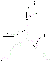
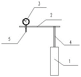
[0025] Such as figure 1 , figure 2 As shown, a crankshaft eccentricity measuring device includes a 90-degree V-shaped positioning block 1, a measuring cantilever 2, a dial indicator 3, and a connecting rod 4. The 90-degree V-shaped positioning block 1 is connected to one end of the measuring cantilever 2 through the connecting rod 4 Below, the other end of the measuring cantilever 2 is provided with a dial indicator 3, and a dial indicator contact 5 is provided under the dial indicator 3.

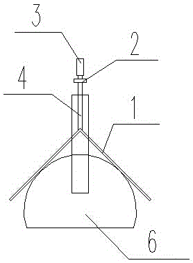
[0026] Use as figure 1 with figure 2 After the crankshaft eccentricity measuring device shown measures the eccentricity of the A-type crankshaft, when the same crankshaft eccentricity measuring device is used to measure the eccentricity of the B-type crankshaft of different crankshafts, as image 3 , Figure 4 , Figure 5 , Image 6 , Figure 7 with Figure 8 As shown, the specific implementation steps are as follows: including the eccentricity measuring device, the reference block 6 of the A...

Embodiment 2)

[0033] Such as figure 1 with figure 2 As shown, a crankshaft eccentricity measuring device includes a 90-degree V-shaped positioning block 1, a measuring cantilever 2, a dial indicator 3, and a connecting rod 4. The 90-degree V-shaped positioning block 1 is connected to one end of the measuring cantilever 2 through the connecting rod 4 Below, the other end of the measuring cantilever 2 is provided with a dial indicator 3, and a dial indicator contact 5 is provided under the dial indicator 3.

[0034] Use as figure 1 with figure 2 After the crankshaft eccentricity measuring device shown measures the eccentricity of the A-type crankshaft, when the same crankshaft eccentricity measuring device is used to measure the eccentricity of the B-type crankshaft of different crankshafts, as image 3 , Figure 4 , Figure 5 , Image 6 , Figure 7 with Figure 8 As shown, the specific implementation steps are as follows: including the eccentricity measuring device, the reference block 6 of th...


PUM


Abstract

The invention relates to the technical field of detection of the eccentric throw of a crankshaft, and especially relates to an apparatus and method of measuring the eccentric throw of a crankshaft. The apparatus comprises a 90-degree V-shaped positioning block, a measuring cantilever and an indicating gauge. During detection, a gauge reference block of a to-be-measured crankshaft is also needed, the apparatus is calibrated and set to be zero on the gauge reference block, and then the apparatus measures the eccentric throw of an A type crankshaft. When the apparatus measures other types of crankshafts such as a B type crankshaft, distances b between the highest points of connecting rod necks of the A type crankshaft and the B type crankshaft and the intersection point of the 90-degree V-shaped positioning block are calculated by means of a mathematical formula shown in the description. According to a difference [delta]b of the distances b of the A type crankshaft and the B type crankshaft, the eccentric throw of the B type crankshaft is obtained through the apparatus and a conversion method. In this way, the step of making a gauge reference block specially for the B type crankshaft is not needed. The difficulty in detection of the eccentric throw of a crankshaft is solved, the problems in borrowing of apparatuses for different procedures of crankshafts with the same type and borrowing of apparatus for different type of crankshafts are solved, and the manufacture cost of the apparatus is greatly reduced.

Description

Technical field [0001] The invention relates to the technical field of crankshaft eccentricity detection, in particular to a crankshaft eccentricity measuring device and a measuring method thereof. Background technique [0002] The crankshaft eccentricity measurement tool is a special tool, which consists of two parts: the eccentricity measurement device and the reference block of the meter. The reference block of the watch is a simulated standard block made according to the size of the crankshaft to be tested. The measuring method is as follows: the eccentricity measuring device first checks the gauge on the reference block to find the maximum value displayed by the dial gauge, adjusts the pointer of the dial gauge to the zero position, and then moves the measuring device to the crankshaft to be measured, outside the main journal For circle positioning, read the dial gauge value by measuring the highest point of the connecting rod neck. The difference between this value and the...

Claims


Application Information

Patent Timeline
Patent Type & Authority Applications(China)
IPC IPC(8): G01B5/252
Inventor 刘德岭张云峰石国栋刘刚
Owner CRRC QISHUYAN CO LTD
Why Eureka
Try Eureka